Card holding member and card connector

a holding member and card technology, applied in the direction of coupling device connection, two-part coupling device, instruments, etc., can solve the problems of short circuit, less dimensional precision, high manufacturing cost, etc., and achieve the effect of high reliability

Active Publication Date: 2017-05-16
MOLEX INC
View PDF3 Cites 2 Cited by
  • Summary
  • Abstract
  • Description
  • Claims
  • Application Information

AI Technical Summary

Benefits of technology

[0009]The card tray of the prior art is integrally molded using a resin material. Therefore, when the card tray is repeatedly inserted into and ejected from the card connector, the side frame portions 964 and the latch member 975 experience wear. As card trays become smaller and thinner to accommodate smaller cards 901, they also become less strong and more likely to be damaged. A technique has therefore been proposed in which a card tray is obtained by sintering a metal powder compact obtained using metal injection molding (MIM). However, this manufacturing technique is expensive and less dimensionally precise.
[0011]It is an object of the present disclosure to solve this problem by providing a highly reliable card holding member and card connector in which short-circuiting does not occur, which are strong, and which are not subject to damage or wear.
[0018]The present disclosure is able to provide a highly reliable card holding member in which short-circuiting does not occur, which is strong, and which is not subject to damage or wear.

Problems solved by technology

However, this manufacturing technique is expensive and less dimensionally precise.
Some of these exposed electrode pads may come into contact with metal on the card tray and cause a short circuit.

Method used


Image

  • Card holding member and card connector
  • Card holding member and card connector
  • Card holding member and card connector

Examples


Embodiment Construction

[0035]The following is a detailed explanation of an embodiment of the present disclosure with reference to the drawings.

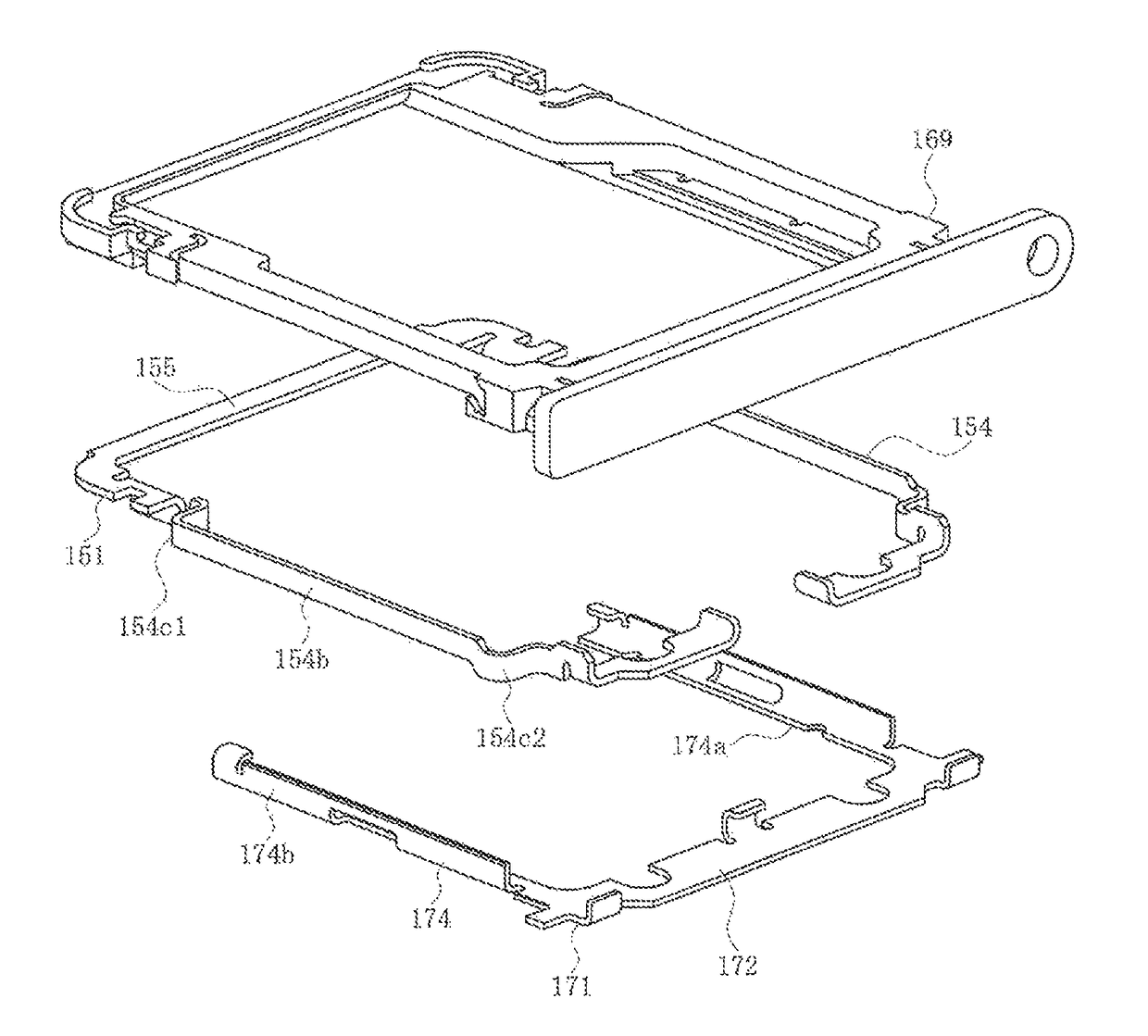
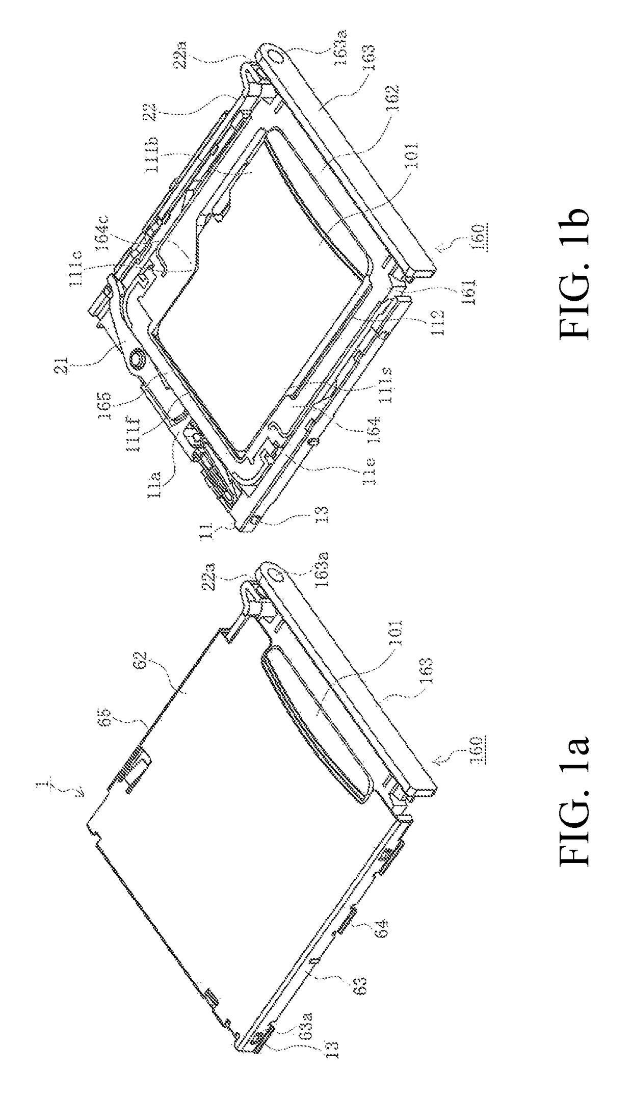
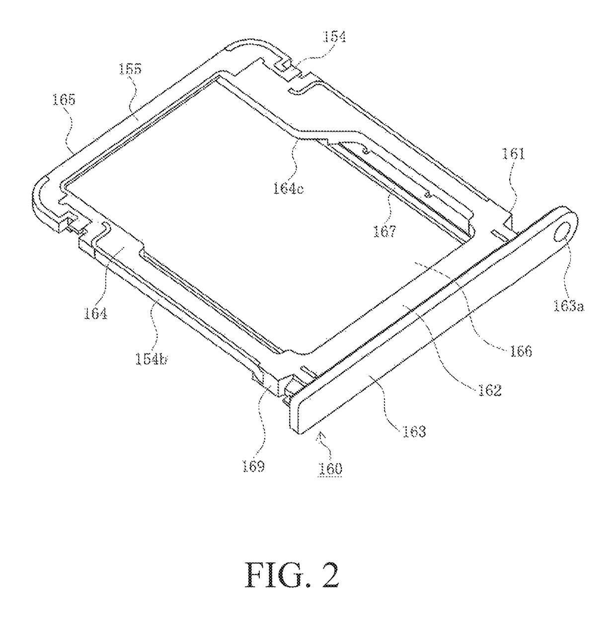
[0036]FIGS. 1(a) and 1(b) are a pair of perspective views of a card tray inserted into a card connector according to an embodiment of the present disclosure. FIG. 2 is a perspective view of the card tray according to an embodiment of the present disclosure. FIGS. 3(a), 3(b), 3(c), 3(d) and 3(e) are a set of five views of the card tray according to an embodiment of the present disclosure. FIG. 4 is a perspective view showing the first member and the second member of the metal portion of the card tray according to an embodiment of the present disclosure. FIG. 5 is a perspective view showing the combined first member and second member of the metal portion of the card tray according to an embodiment of the present disclosure. FIG. 6 is an exploded view of the card tray in an embodiment of the present disclosure. FIGS. 7(a) and 7(b) are a pair of cutaway views of the ca...


PUM


Abstract

The card holding member is able to hold a card having terminal members and is able to be inserted into a card connector, and includes a frame portion opposing the side surfaces of the card. The frame portion includes a first metal portion composed of a metal plate, a second metal portion composed of a metal plate being a separate component from the first metal portion, and a resin portion surrounding and covering at least a portion of the first metal portion and the second metal portion.

Description

RELATED APPLICATIONS[0001]This application claims priority to Japanese Application No. 2014-244749, filed Dec. 3, 2014, which is incorporated herein by reference in its entirety.TECHNICAL FIELD[0002]The present disclosure relates to a card holding member and to a card connector.BACKGROUND ART[0003]Electronic devices such as mobile phones include a card connector enabling the use of various types of cards such as SIM (Subscriber Identity Module) cards.[0004]Electronic devices have become significantly smaller in recent years, and so have cards and card connectors. As a result, it can be difficult for users to grasp a card with the fingers and insert the card properly into a card connector. Therefore, card connectors have been proposed in which a card is set inside a card holder and the card holder is inserted into the card connector (see, for example, Patent Document 1).[0005]FIG. 9 is a perspective view of a card tray and a card connector of the prior art.[0006]In this drawing, 961 ...

Claims


Application Information

Patent Timeline
Patent Type & Authority Patents(United States)
IPC IPC(8): H01R24/00G06K13/08
CPCG06K13/08
Inventor NAGASE, TERUKISHIMOTSU, AKIHIRO
Owner MOLEX INC
Why Eureka
Try Eureka