Ultrasonically visible medical balloon assembly

a technology of ultrasonic/sonic/infrasonic image and balloon, which is applied in the direction of catheter, application, ultrasonic/sonic/infrasonic image/data processing, etc., can solve the problems of difficult to see during imaging and not always optimal

Inactive Publication Date: 2016-06-23
COOK MEDICAL TECH LLC
View PDF8 Cites 0 Cited by
  • Summary
  • Abstract
  • Description
  • Claims
  • Application Information

AI Technical Summary

Problems solved by technology

A problem arises with such balloon catheters, however, in that they are difficult to see during imaging.
Although it is possible to use imaging materials, such as contrast media, during the deployment of such balloons, the r

Method used


Image

  • Ultrasonically visible medical balloon assembly
  • Ultrasonically visible medical balloon assembly
  • Ultrasonically visible medical balloon assembly

Examples


Embodiment Construction

[0030]It is to be understood that the drawings are schematic only and not to scale. They are intended to depict the major components of the devices taught herein and minor or ancillary components are not shown for the sake of clarity. The skilled person will be well acquainted with the typical dimensions and proportions suitable for the components and devices shown in the drawings, particularly having regard to the accompanying description.

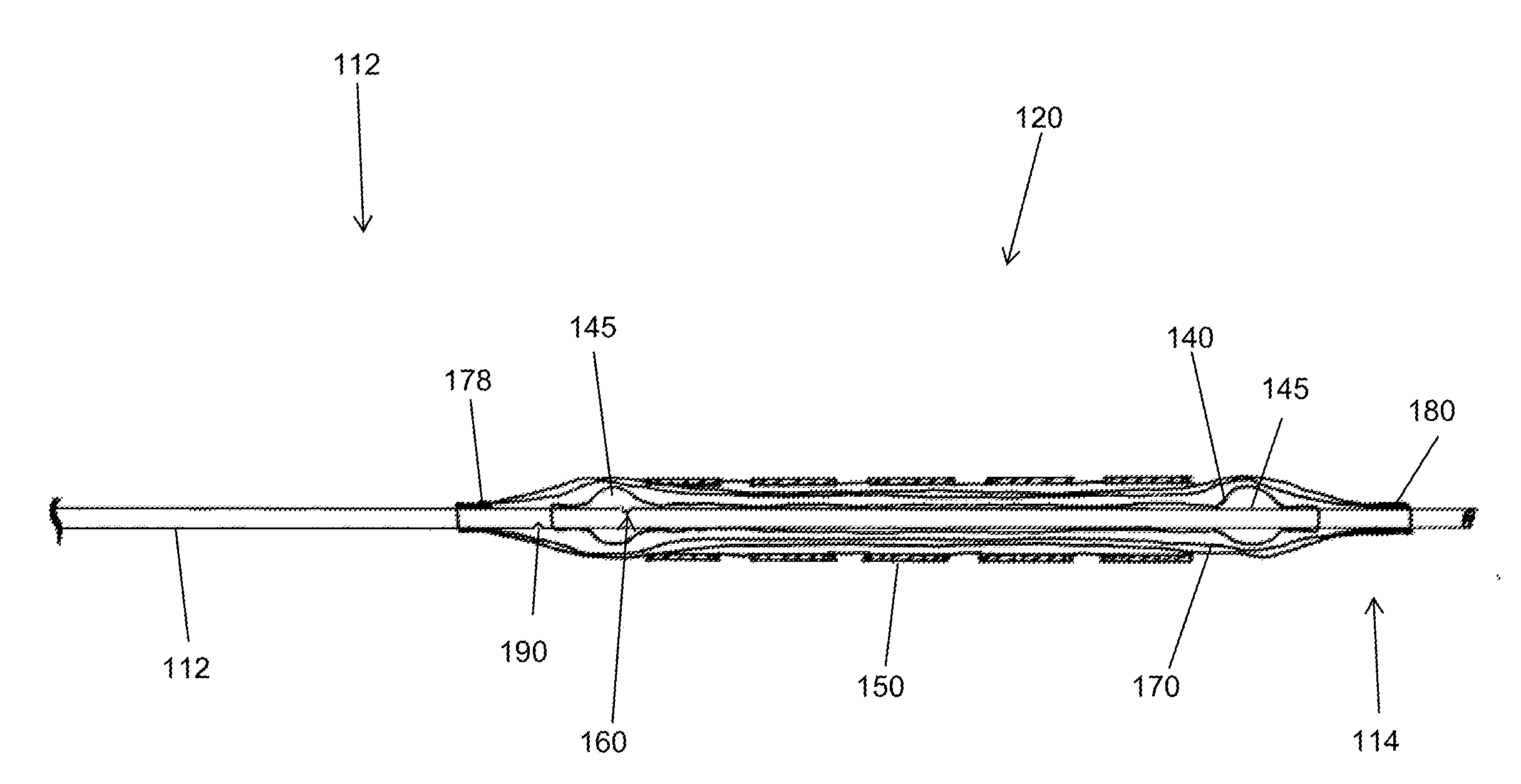
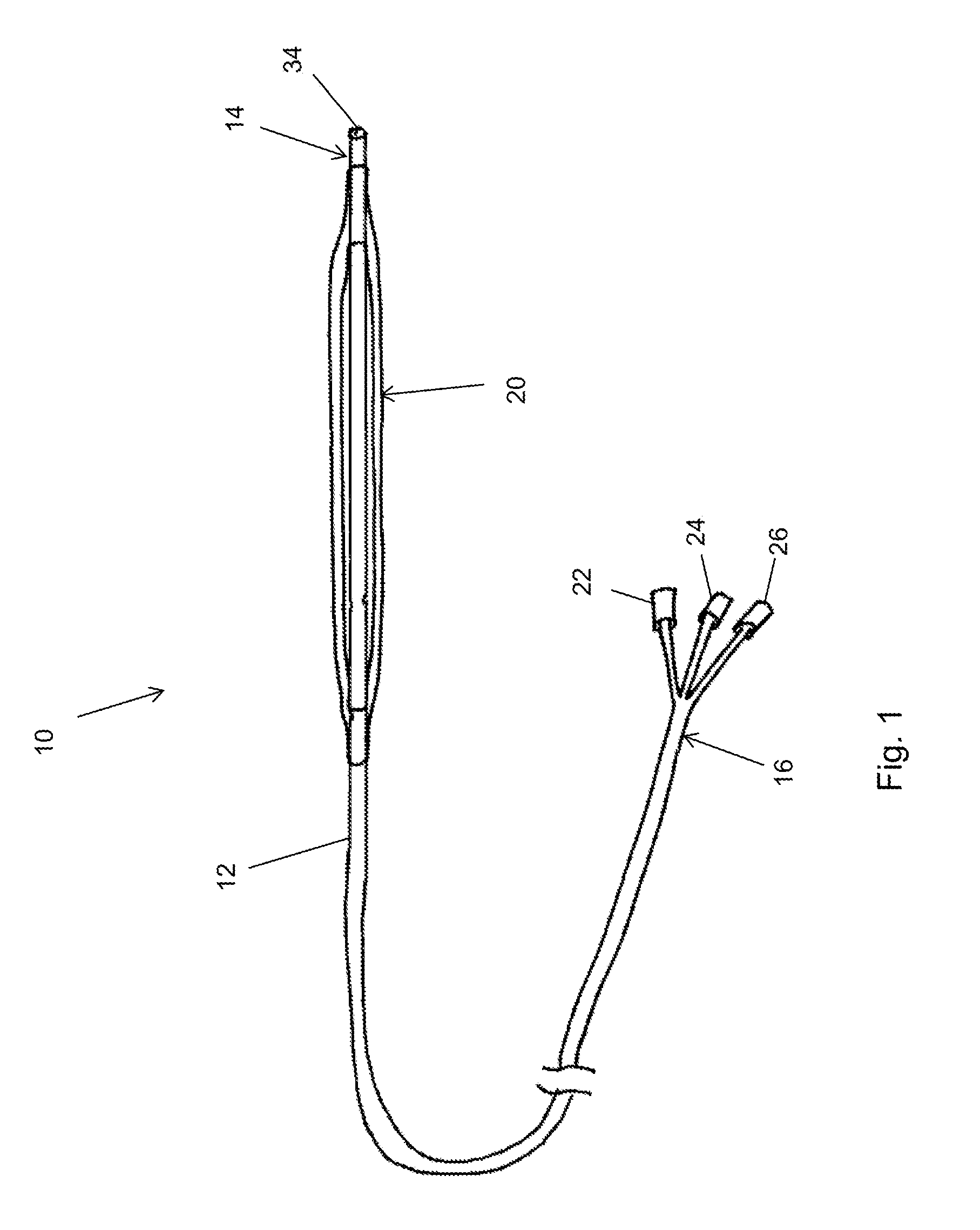
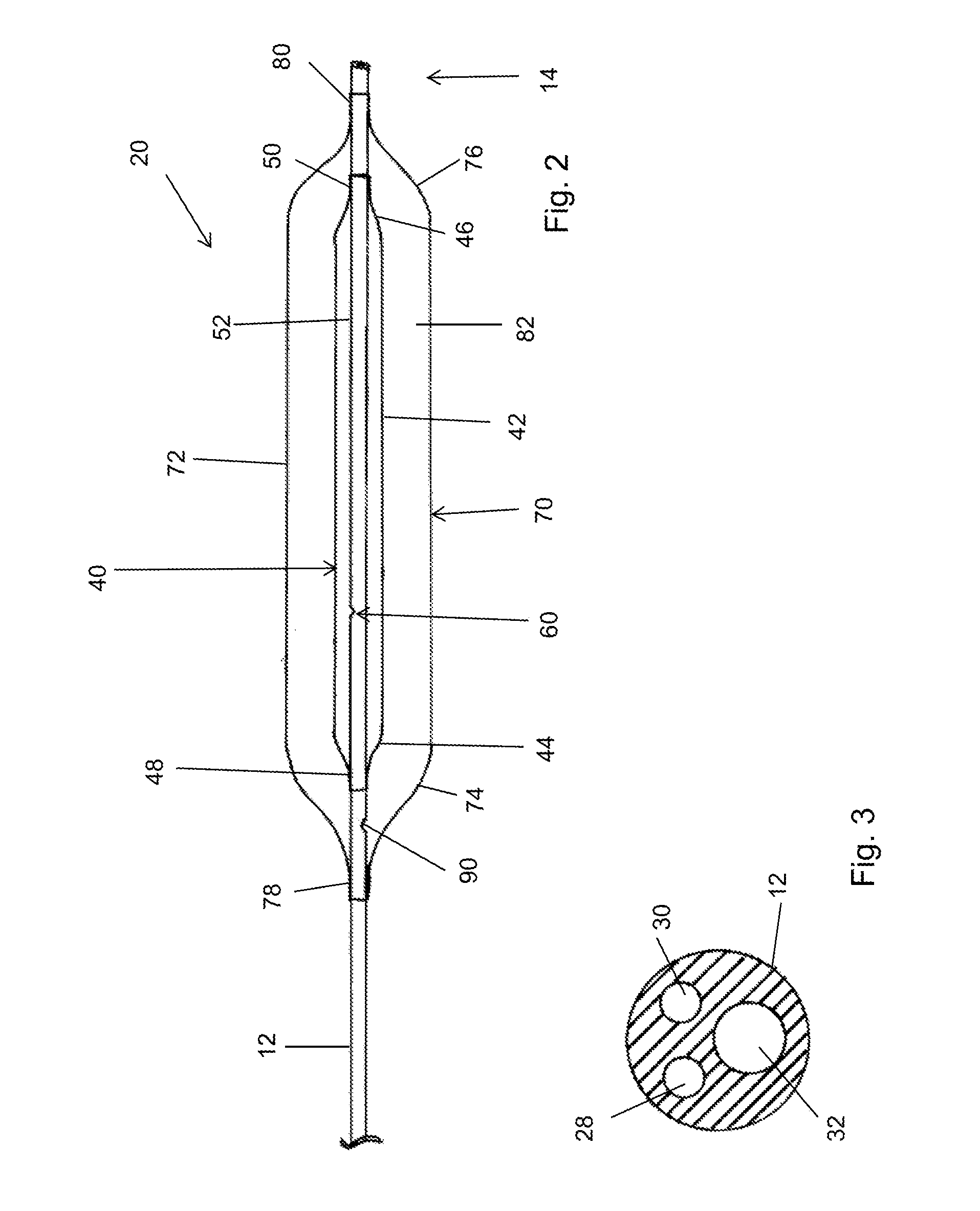
[0031]Referring first to FIG. 1, this shows in schematic form an embodiment of balloon catheter assembly 10 according to the teachings herein. The assembly 10 includes an elongate catheter 12 having a distal end 14 and a proximal end 16. The catheter 12 is of a length such that the proximal end 14 can be positioned endoluminally at a treatment site in a vessel of a patient with the proximal end 16 remaining outside the patient. Typically, the catheter 12 may length from a few tens of centimetres to one metre or even longer, as required.

[0032]By th...


PUM


Abstract

A balloon catheter assembly (10) includes a balloon structure (20) formed of an inner balloon (40) and an outer balloon (70) which entirely envelops the inner balloon (40). The inner balloon (40) can be filled with air or other echogenic fluid and inflates to a diameter substantially less than the inflated diameter of the outer balloon (70), typically to a diameter of no more than 50% of the inflated diameter of the outer balloon (70). The inner balloon (40) can be inflated with air or other echogenic fluid, enabling the balloon structure (20) to be visible under ultrasonic imaging. The inner balloon (40) is protected within the outer balloon (70) and is shorter than the outer balloon (70). The assembly (10) can be used for PTA procedures, for deploying an implantable medical device or for other medical applications.

Description

CROSS-REFERENCE TO RELATED APPLICATIONS[0001]This application claims priority to GB application no. 1422607.0, filed Dec. 18, 2014, titled “ ULTRASONICALLY VISIBLE MEDICAL BALLOON ASSEMBLY,” the contents of which application is incorporated herein by reference.TECHNICAL FIELD[0002]The present invention relates to a balloon catheter assembly, which may in example implementations be configured as a PTA balloon or a device deployment balloon.BACKGROUND ART[0003]Medical balloon assemblies are known in the art, for use for example in angioplasty procedures, for deploying implantable medical devices, and so on.[0004]Medical balloons are typically made of a fine yet strong polymer material, such as polyethylene terephthalate (PETE), polyamide (Nylon) or the like, and are fitted to a balloon catheter, also typically made of a polymer material. These materials have the advantage of being biocompatible, being strong in use and also being flexible, which assists in the trackability of the appa...

Claims


Application Information

Patent Timeline
IPC IPC(8): A61M25/10A61B8/08
CPCA61M25/104A61M2025/1013A61M25/1011A61B8/481A61M25/0108A61M2025/1004A61M2025/1093A61F2/958
Inventor AGGERHOLM, STEENBOUWMAN, LEE HANSKRASZNAI, ATILLA GYORGYLYSGAARD, THOMASMOELLER, RASMUS BUCH
Owner COOK MEDICAL TECH LLC
Why Eureka
Try Eureka