Dual lumen surgical hand-piece with ultrasonic knife

a technology of hand-pieces and ultrasonic knives, which is applied in the field of hand-pieces for surgery, can solve the problems of not having ultrasonic vibration capability, unable to be sure that all tissue has been broken up, and subjecting patients to increased possibilities of infection and trauma, and achieves the effect of less expensive and easy manufacturing of work tips

Active Publication Date: 2020-07-14
SURGICAL DESIGN
View PDF43 Cites 0 Cited by
  • Summary
  • Abstract
  • Description
  • Claims
  • Application Information

AI Technical Summary

Benefits of technology

[0021]In accordance with the invention a surgical hand piece is provided with a solid ultrasonic knife or scalpel made of titanium alloy or a material that is less expensive and easier to manufacture than titanium. Further, plastic or other inexpensive tubes can be provided next to the knife blade to provide both aspiration and irrigation. Thus, instead of the titanium needle providing emulsification, irrigation and aspiration, these functions are separated according to the present invention. Thus, only the emulsification function is carried out by a metal blade and the other functions can be carried out with less strong and less expensive tubes laid next to the metal blade. Further, the operation of the aspiration and irrigation tubes can be reversed as needed for phacoemulsification and cleanup.
[0025]The principles of the invention have numerous advantages. For example, the invention allows for a less expensive and easier to manufacture work tip because of the solid knife instead of the single or dual tubes. In addition, the design of the present invention allows the work piece to be used both for phacoemulsification and clean up without having to remove the work piece from the surgical site, such as the eye, and to replace it with an I / A clean up tool. Further, according to the present invention, clean up can be commenced without the surgeon having to divert his attention from the eye of the patient.

Problems solved by technology

Such an instrument typically has concentric infusion and aspiration lumens, and typically has no ultrasonic vibration capability.
Also, the I / A tool has a disadvantage in that the surgeon would have to keep inserting and withdrawing the ultrasonic work tip and the I / A tool from the eye as the process is completed, because the surgeon cannot be sure that all of the tissue has be broken up until the cleanup process has begun.
As a result, this would also subject the patient to the increased possibilities of infection and trauma.
Titanium, however, is a material that is hard to work with and is expensive.
However, as the surgical cost has come down and since there has been increased pressure to reduce medical costs; the cost of the needle has become significant.
With this design, not only are there two titanium tubes, but their proximal ends have significant bends that prove to be a manufacturing challenge when titanium is used.
The problem is that this disposable work tip creates even more impetus to reduce its cost.

Method used


Image

  • Dual lumen surgical hand-piece with ultrasonic knife
  • Dual lumen surgical hand-piece with ultrasonic knife
  • Dual lumen surgical hand-piece with ultrasonic knife

Examples


first embodiment

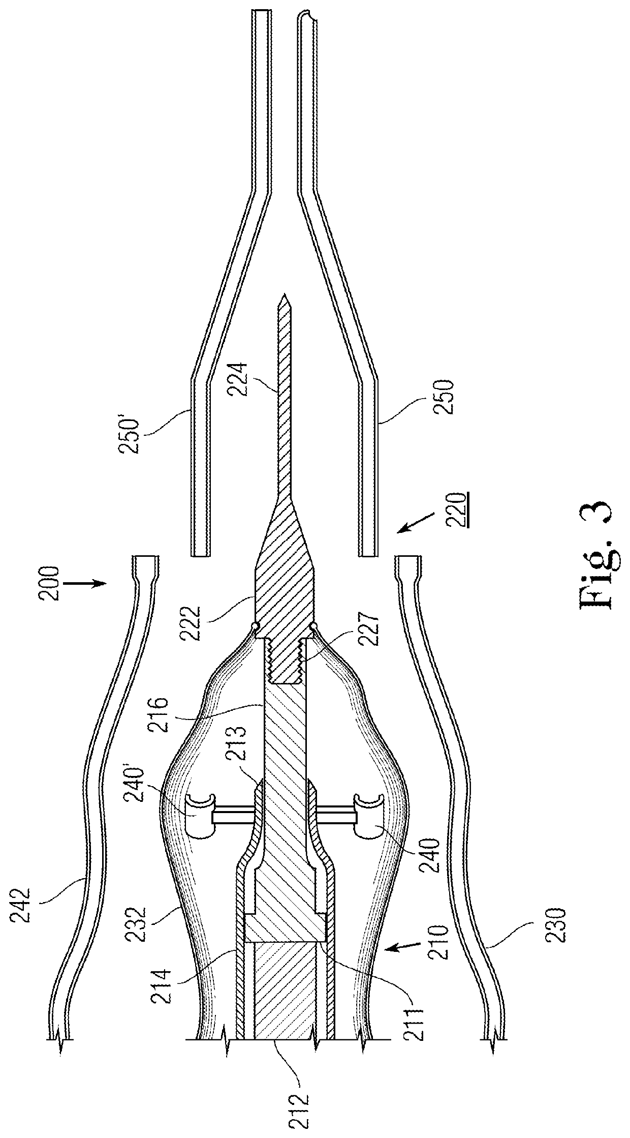
[0035]FIG. 3 shows an exploded view of a handpiece 200 according to an illustrative first embodiment of the present invention. This hand piece has an ultrasonic vibration part 210 connected to a disposable work piece 220. The vibration part has a housing 214. A transducer 212 is provided in part 210 for generating ultrasonic linear mechanical vibrations upon excitation with an alternating-current electrical signal. The transducer is supported within the housing 210 by flanges 211. A metal connecting body 216 having a reduced diameter distal end portion is attached to the transducer 212. The connecting body forms an acoustic impedance transformer for conveying the longitudinal vibrations of the transducer 212 for application to the operative working tip 220 connected to the distal end of the connecting body 216. Further, the housing has a part 213 that engages the connecting body 216 at a null point in its vibration to provide further support.

[0036]The work tip 220 has a hub 222. In ...

second embodiment

[0043]As a second embodiment and as shown in FIG. 5A, the bands 260 can be replaced with a plastic sleeve 226 that surrounds the hub and knife. Its proximal end is larger to accommodate the hub. This larger end is reduced in size toward its distal end so as to form about the knife. As a result, a relatively uniform channel 225 is created between the inner surface of the outer shell 226 and the combination hub and knife. The channel 225 extends from the distal end of the work piece 220, but is blocked by O-ring 223 at the end of the sleeve 226. This O-ring also keeps fluid from the surgical site from traveling along the knife and exiting the work tip beyond the hub. Also, it tends to isolate the vibration of the knife from the structure of the tubes 250, 250′. Basically the tube holders 240, 240′ are fastened to the housing 214, which is stationary. Therefore the holders are relatively stable. The holders engage rigid tubes 250, 250′ so they are stable with respect to the knife which...

third embodiment

[0045]A third embodiment shown in FIG. 6A has tubes 250, 250′ located inside a sleeve 226′. These tubes penetrate the sleeve distal of an O-ring 223. Rather than being circular, like that in FIG. 5A, the tube 250′ inside the sleeve 226′ has a semicircular shape. On the other hand, tube 250 has a circular shape. Both of these tubes are on opposite sides a channel 225 in which the vibration knife is located. As with the design of FIG. 5A, the proximal end of channel 225 is blocked by O-ring 223.


PUM


Abstract

A surgical hand piece has a solid surgical knife connected to a source of ultrasonic energy. Two or more rigid plastic irrigation and aspiration tubes are provided alongside the knife and they may be supported with respect to the knife by tube holders fastened to the hand piece housing for the source of ultrasonic energy. The rigid plastic tubes may be connected toward their distal ends by a support in the form of bands about the tubes and knife, a sleeve about the tubes and knife or a sleeve about the knife with the tubes supported on the external surface thereof.

Description

TECHNICAL FIELD[0001]The present invention is generally directed to hand pieces for surgery, particularly for the removal of cataracts from the eye of a patient by phacoemulsification.BACKGROUND OF THE INVENTION[0002]The use of instruments in ocular surgical applications is well known. One widely used type of instrument is an ultrasonic hand piece that is used in ophthalmic applications, such as in the removal of cataracts from the eye by phacoemulsification.[0003]FIG. 1 depicts one such type of prior art ultrasonic hand piece as shown in U.S. Pat. No. 4,504,264 of Kelman. This hand piece has a housing 10 of, for example, plastic or metal, within which is supported a transducer means 11 for generating mechanical vibrations upon excitation with an alternating-current electrical signal. The transducer 11 is shown as a magnetostrictive transducer with an electrical coil 12 wound about a stack of metal laminations so that longitudinal mechanical vibrations are produced. The transducer c...

Claims


Application Information

Patent Timeline
Patent Type & Authority Patents(United States)
IPC IPC(8): A61F9/007A61M1/00A61B17/32A61M3/02A61F9/008
CPCA61M1/0064A61F9/00745A61F2009/00887A61B2217/005A61F9/008A61B2017/32007A61M3/0283A61B2017/320084A61F2009/0087A61M2210/0612A61M1/774
Inventor BANKO, WILLIAM
Owner SURGICAL DESIGN
Why Eureka
Try Eureka