Waterproof control unit and method of assembling the same

a technology of control unit and hood, which is applied in the direction of electrical apparatus casing/cabinet/drawer, coupling device connection, hermetically sealed casing, etc., can solve the problems of large weight, long body of connector, and inapplicability of die formed connector to casing using the cover

Active Publication Date: 2017-05-23
MITSUBISHI ELECTRIC CORP
View PDF32 Cites 1 Cited by
  • Summary
  • Abstract
  • Description
  • Claims
  • Application Information

AI Technical Summary

Benefits of technology

[0024]It is a first object of the present invention to provide a waterproof control unit that uses a common connector housing applicable to both a cover subjected to forming or sheet metal working and a base subjected to forming or sheet metal working, and can ensure a necessary sealing path while preventing the connector housing from having a long body dimension.
[0025]It is a second object of the present invention to provide a waterproof control unit in which a sealing gap does not fluctuate significantly due to dimension fluctuations of components, the waterproof control unit being capable of suppressing, in a case where the connector housing is shaken in an up-and-down direction at the time of operation of inserting or removing the mating connector, application of an excessively large external force to the sealing gap so as to prevent sealing surfaces from peeling off, and capable of easily assuming, by visual observation, whether or not a proper amount of a sealing material is filled and applied to the sealing gap.

Problems solved by technology

Therefore, when the lower case 30 is formed by, for example, aluminum die casting and the upper case 20 is formed of, for example, a resin forming material, there is a problem in that the entire weight becomes larger.
Further, there is a problem in that the connector formed by the die is not applicable to the casing using the cover (upper case) or the base (lower case) made of a sheet metal material.
Therefore, there is a problem in that the connector has a long body.
Therefore, in a case where the connector housing manufactured by the die is used in combination with the resin cover or the base formed by aluminum die casting, the connector has an unnecessarily long body, and hence there is a problem in that increase in electrical resistance of a connector pin cannot be suppressed.
Accordingly, there are problems in that the connector 15 has a long body dimension, and that it is difficult to perform applying work of the waterproof sealing material to the first sealing gap.
Further, the third sealing gap between the cover 13 and the case 12 is formed into the sealing gap having a narrow width in such a manner that the outer peripheral bending end surface of the cover 13 is fitted into the concave thread formed in the outer periphery of the case 12, and hence there is a problem in that the case made of a sheet metal material cannot be used.
Thus, there is a problem in that, when a gap dimension A between the protruding portion 61 and the hollow portion 62 is increased due to dimension fluctuations of the respective portions, it is impossible to obtain an effect of suppressing shifting of the connector 15 at the time of operation of inserting or removing the mating connector.

Method used


Image

  • Waterproof control unit and method of assembling the same
  • Waterproof control unit and method of assembling the same
  • Waterproof control unit and method of assembling the same

Examples


first embodiment

(3) Main Points and Features of First Embodiment

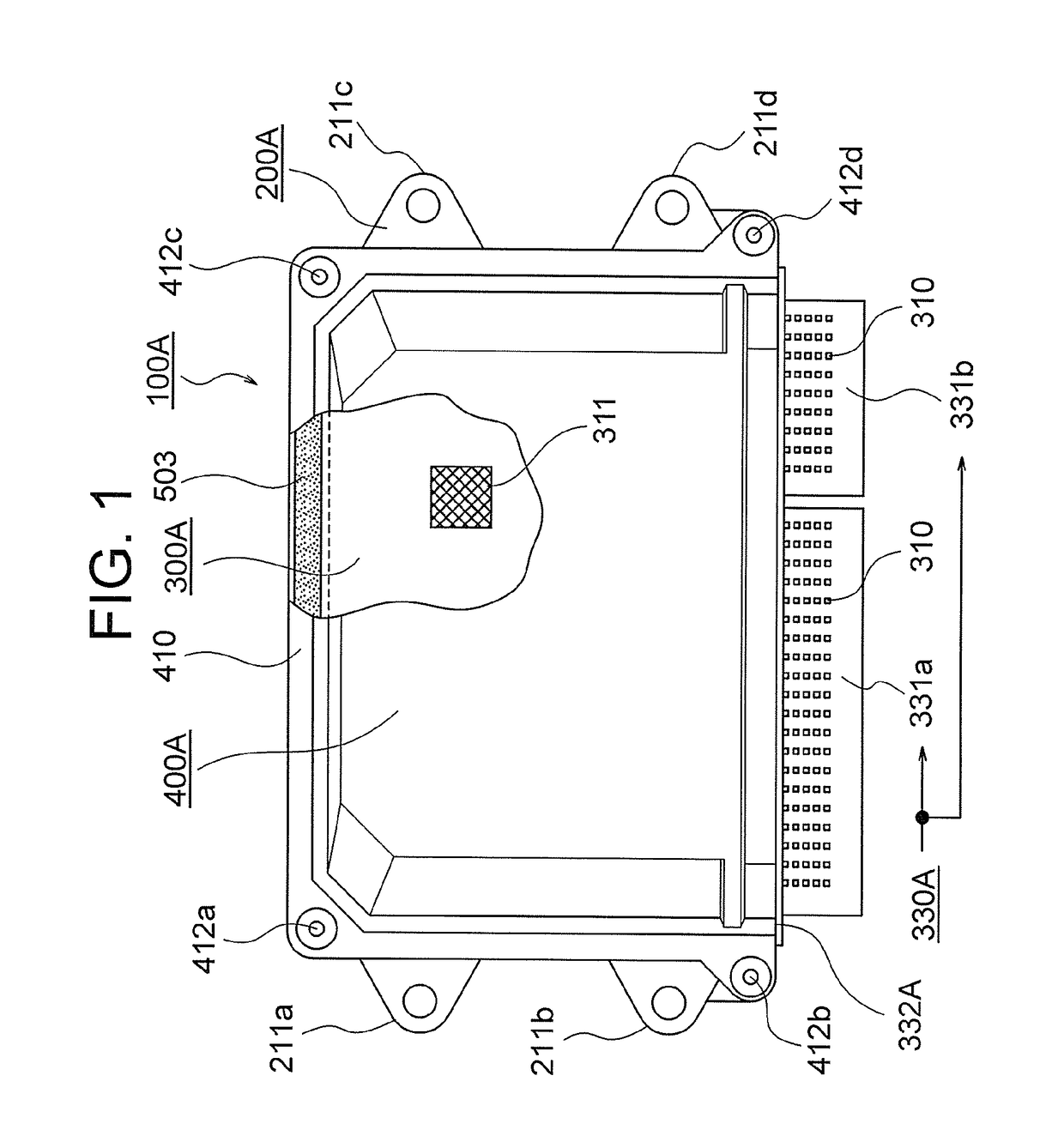
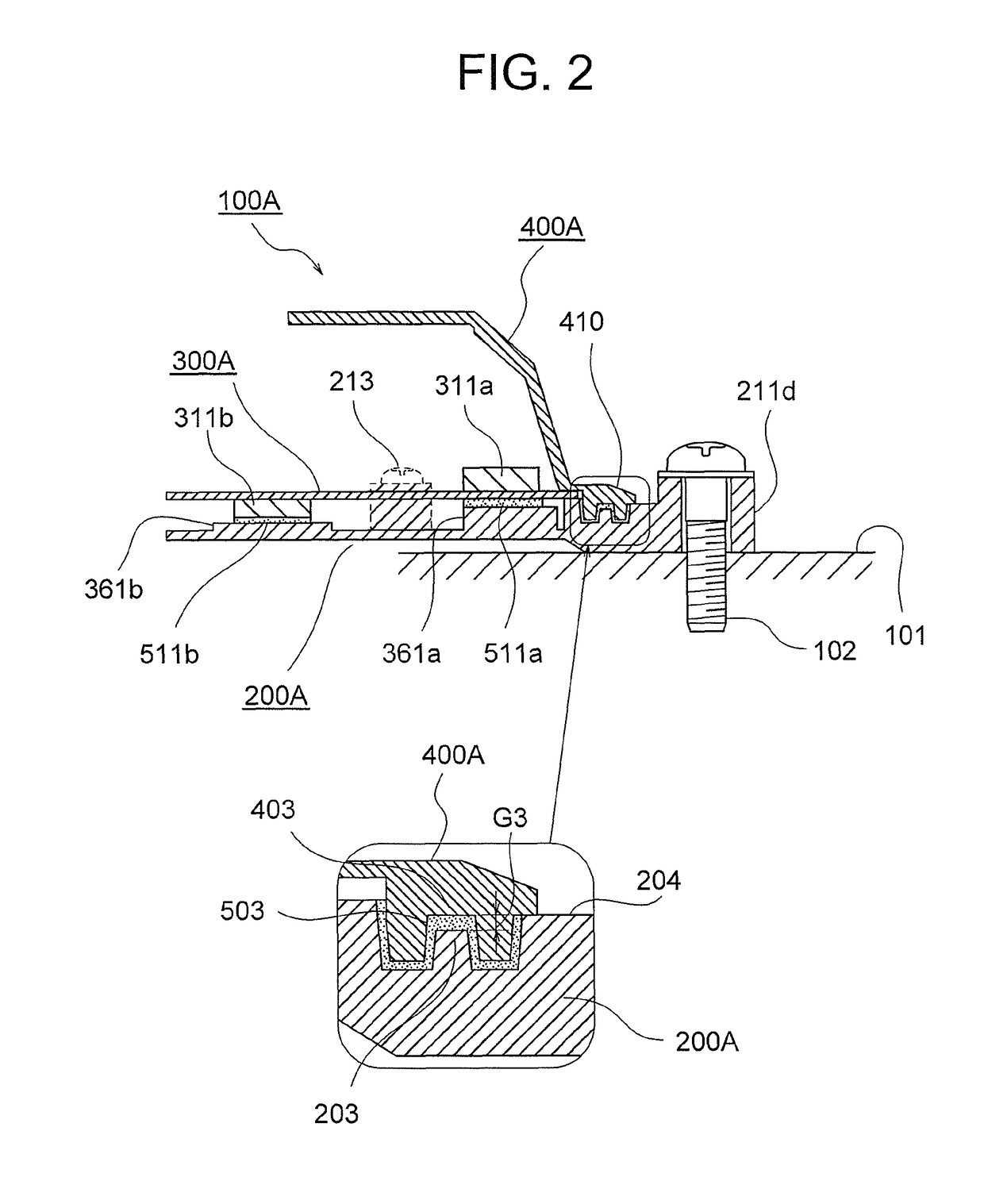
[0144]As is apparent from the above description, the waterproof control unit 100A according to the first embodiment of the present invention includes:

[0145]the base 200A and the cover 400A;

[0146]the circuit board 300A that is hermetically housed in a casing including the base 200A and the cover 400A, and has the circuit components 311 mounted thereon;

[0147]the connector housing 330A that is positioned and fixed to the circuit board 300A, and allows the plurality of contact terminals 310 to pass therethrough via the partition wall 333; and

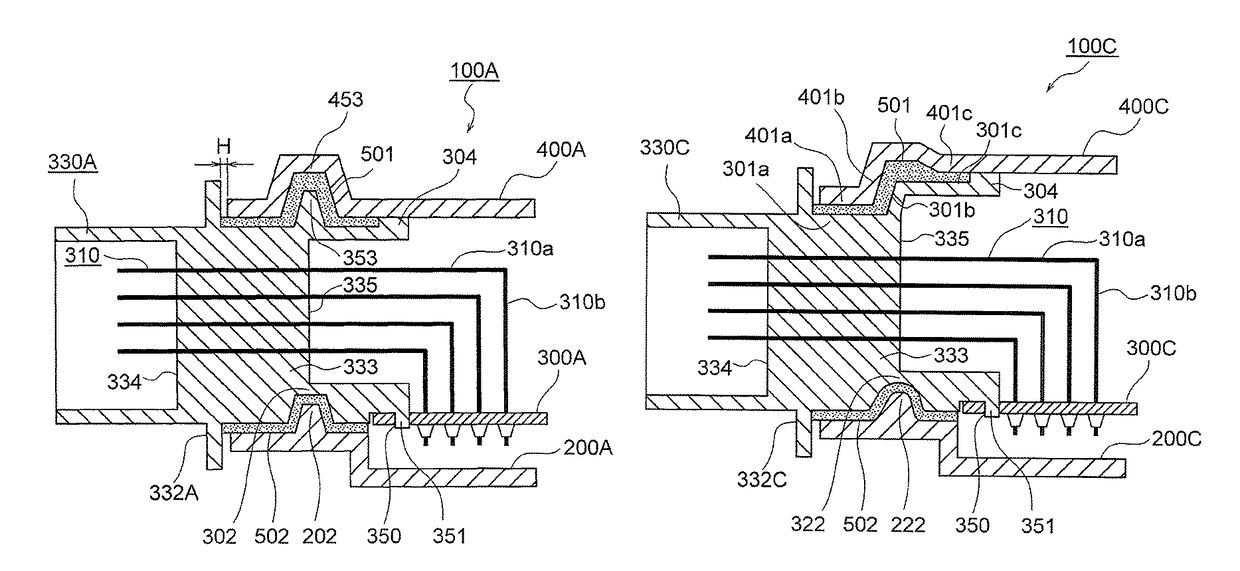
[0148]waterproof sealing materials 501, 502, and 503 filled into the first sealing gap defined between opposing surfaces of the connector housing 330A and the cover 400A, the second sealing gap defined between opposing surfaces of the connector housing 330A and the base 200A, and the third sealing gap defined between directly-opposing surfaces of the base 200A and the cover 400A, so as to expose, from ...

second embodiment

(3) Main Points and Features of Second Embodiment

[0251]As is apparent from the above description, in the waterproof control unit 100B according to the second embodiment of the present invention, the connector housing 330B through which the plurality of contact terminals 310 pass via the partition wall 333 is positioned and fixed to the circuit board 300B, which is hermetically housed in the casing including the base 200B and the cover 400B and has the circuit components 311 mounted thereon. The waterproof control unit 100B includes the waterproof sealing materials 501, 502, and 503 filled into the first sealing gap defined between opposing surfaces of the connector housing 330B and the cover 400B, the second sealing gap defined between opposing surfaces of the connector housing 330B and the base 200B, and the third sealing gap defined between directly-opposing surfaces of the base 200B and the cover 400B, so as to expose, from the opening portion of the side surface of the cover 400...

third embodiment

(4) Main Points and Features of Third Embodiment

[0334]As is apparent from the above description, in the waterproof control unit 100C according to the third embodiment of the present invention, the connector housing 330C through which the plurality of contact terminals 310 pass via the partition wall 333 is positioned and fixed to the circuit board 300C, which is hermetically housed in the casing including the base 200C and the cover 400C and has the circuit components 311 mounted thereon. The waterproof control unit 100C includes the waterproof sealing materials 501, 502, and 503 filled into the first sealing gap defined between opposing surfaces of the connector housing 330C and the cover 400C, the second sealing gap defined between opposing surfaces of the connector housing 330C and the base 200C, and the third sealing gap defined between directly-opposing surfaces of the base 200C and the cover 400C, so as to expose, from the opening portion of the side surface of the cover 400C,...


PUM


Abstract

In a waterproof control unit in which a part of a connector housing mounted on a circuit board is exposed and the circuit board is hermetically housed in a casing including a base and a cover, a sealing gap between the cover and the connector housing is defined between fitting surfaces of a first concave thread and a first convex thread, and a waterproof sealing material is applied to the sealing gap. A waterproof sealing material is applied to the latter sealing gap. Each of the sealing gaps extends inward and outward across an inner boundary surface of a partition wall of the connector housing. Plane movement of each of the sealing gaps is restricted by side-surface convex threads and side-surface concave threads.

Description

BACKGROUND OF THE INVENTION[0001]1. Field of the Invention[0002]The present invention relates to an improvement of a waterproof control unit, which is an on-vehicle electronic control device to be mounted in, for example, an engine compartment, and also relates to an improvement of a method of assembling the waterproof control unit.[0003]2. Description of the Related Art[0004]There have been widely used waterproof control units including a casing including a base and a cover, and a circuit board hermetically housed in the casing, onto which a circuit component and a plurality of external connection contact terminals are mounted, and a connector housing made of a resin forming material is positioned and fixed. The waterproof control units further include, in order to expose, from the casing, an end surface of the connector housing having the plurality of contact terminals passing therethrough, waterproof sealing materials filled into a first sealing gap defined between abutment surfa...

Claims


Application Information

Patent Timeline
Patent Type & Authority Patents(United States)
IPC IPC(8): H05K5/06H05K7/20H01R13/52H05K3/28H05K3/34H05K5/00
CPCH05K5/062H01R13/5202H05K3/28H05K3/341H05K5/0056H05K7/20445
Inventor NURIYA, NOBUAKINISHIDA, MITSUNORI
Owner MITSUBISHI ELECTRIC CORP
Why Eureka
Try Eureka