
Fastening structure for bicycle rack

a technology for fixing structures and bicycle racks, applied in vehicle components, supplementary fittings, towing devices, etc., can solve problems such as deformation of the hole of the connecting rod, abraded members, and inability to disassemble smoothly

Active Publication Date: 2017-05-30
KING ROOF INDAL
View PDF17 Cites 14 Cited by
  • Summary
  • Abstract
  • Description
  • Claims
  • Application Information

AI Technical Summary

Benefits of technology

The present invention provides a secure way to attach a bicycle rack to a vehicle. A special tool is used to insert an adjusting member between the connection rod and the assembly rod, preventing it from coming loose. The connection rod and assembly rod are also assembled more securely, making this an improved and reliable attachment for bicycles.

Problems solved by technology

However, in this type of convention bicycle rack structure, there is a gap between the connecting rod and the assembling rod and cannot be assembled with each other stably; therefore, when a user is driving the automobile, the adjusting member and the connecting rod shakes, the adjusting member may squeeze with the connecting rod and the assembling rod, and following problems may happen: the adjusting member bends, a thread of the adjusting member is abraded and a through hole of the connecting rod deforms.
If the adjusting member and the connecting rod are not connected to each other tightly, the adjusting member cannot be disassembled smoothly, or the adjusting member may fall off and cause the bicycle rack to be disassembled from the body of the automobile.

Method used


Image

  • Fastening structure for bicycle rack
  • Fastening structure for bicycle rack
  • Fastening structure for bicycle rack

Examples


Embodiment Construction

[0019]The present invention will be clearer from the following description when viewed together with the accompanying drawings, which show, for purpose of illustrations only, the preferred embodiment in accordance with the present invention.

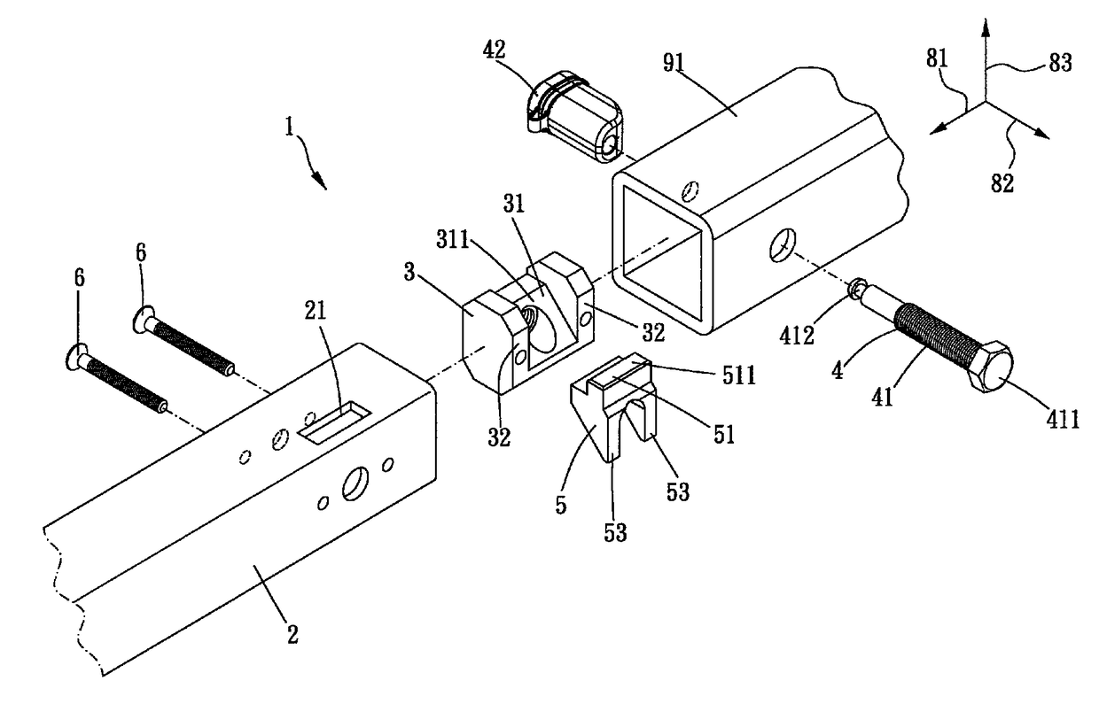
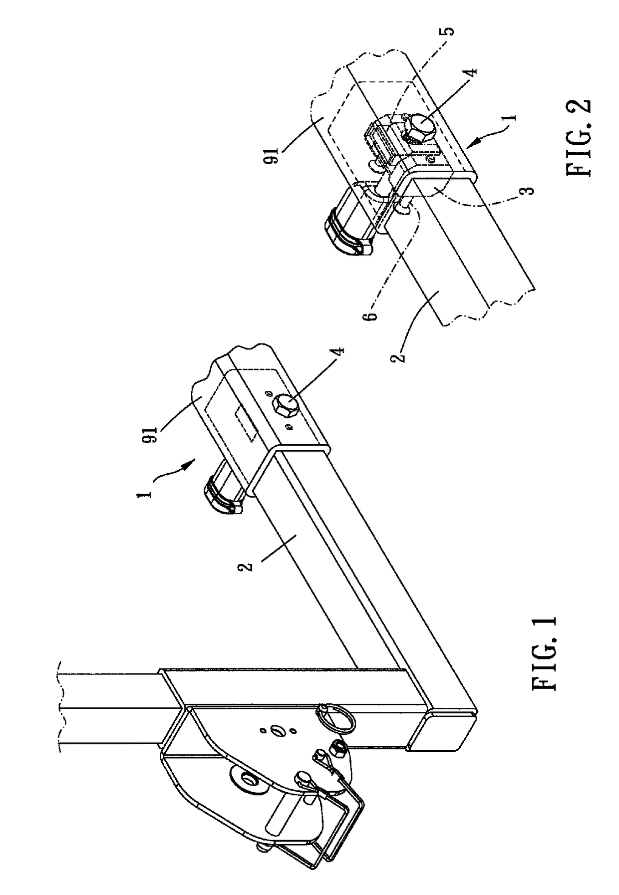
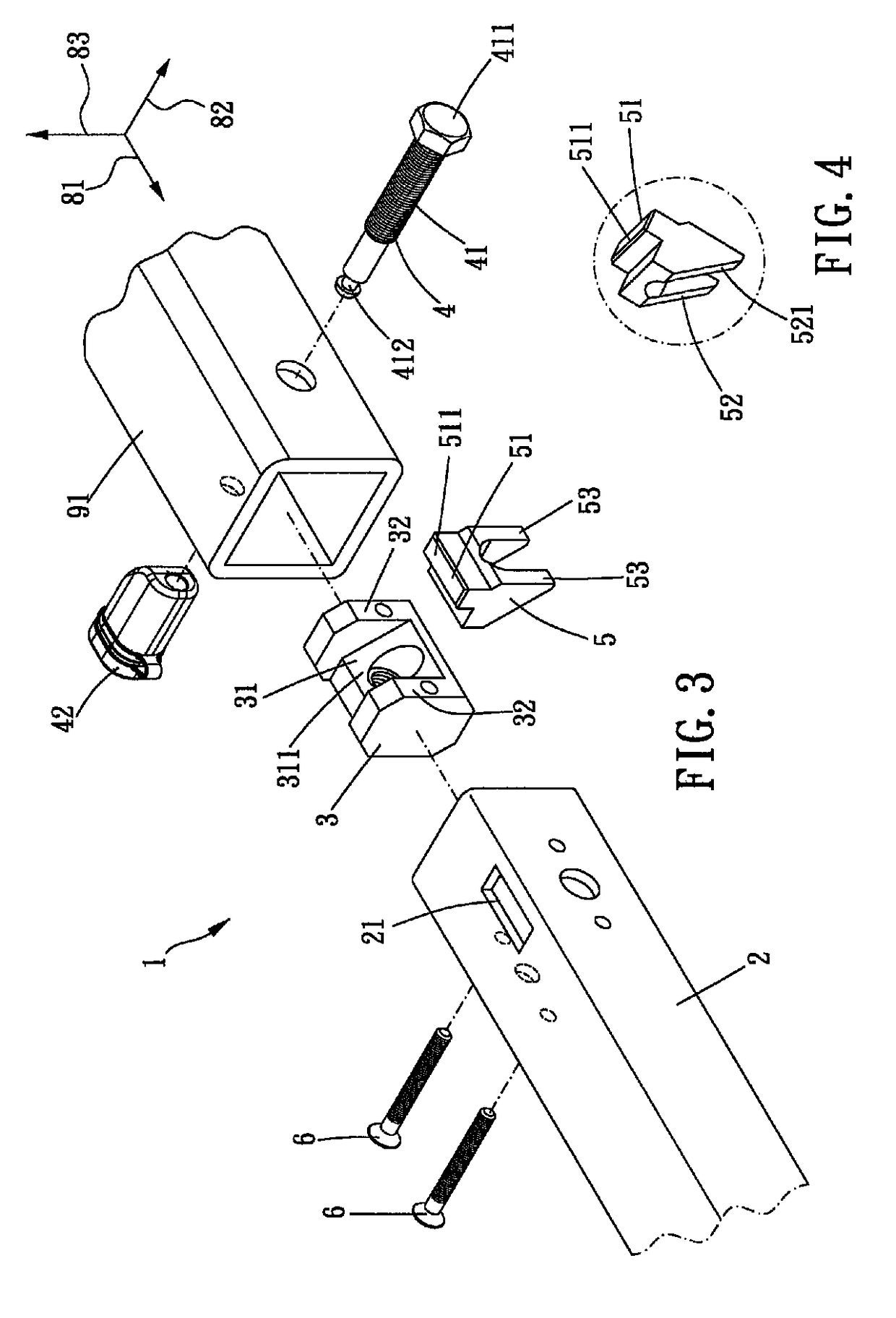
[0020]Please refer to FIGS. 1 to 7 for a preferred embodiment of the present invention. A fastening structure 1 for bicycle rack is for being connected and fastened to an assembling rod 91 of an automobile 9, including a connection rod 2, a slidable member 3, an adjusting member 4 and an abutting block 5.

[0021]The connection rod 2 is inserted in the assembling rod 91 of the automobile 9, the connection rod 2 defines a first direction 81 along a longitudinal direction (as shown in FIG. 3), defines a second direction 82 perpendicular to the first direction 81, and further defines a third direction 83 perpendicular to the first direction 81 and the second direction 82. The connection rod 2 includes a restriction hole 21 along the third direction 83....


PUM


Abstract

A fastening structure for bicycle rack includes a connection rod, a slidable member, an adjusting member and an abutting block. The connection rod is inserted into an assembling rod of an automobile. First, second and third directions are defined to be perpendicular to one another, and the connection rod includes a restriction hole along the third direction. The slidable member is slidably arranged in the connection rod and has a first abutted portion. The adjusting member is disposed through the assembling rod and the connection rod along the second direction, assembled to the slidable member in the connection rod, and slidable between first and second positions along the second direction. The abutting block is arranged in the connection rod and has an abutting portion and a second abutted portion, and the first abutted portion abuts against the second abutted portion.

Description

BACKGROUND OF THE INVENTION[0001]Field of the Invention[0002]The present invention relates to a fastening structure, and more particularly to a fastening structure for bicycle rack.[0003]Description of the Prior Art[0004]People nowadays like to conduct outdoor activities to relax on weekends. For carrying a bicycle conveniently when going out, people puts the bicycle on a bicycle rack to connect the bicycle rack with a body of an automobile. The body of the automobile has an assembling rod, the bicycle rack has a connecting rod, the connecting rod is inserted into the assembling rod, and an adjusting member (a pin) is disposed through and fix the connecting rod and the assembling rod so as to prevent the connecting rod and the assembling rod from being disassembled from each other. This type of bicycle rack structure is disclosed in TWM473345.[0005]However, in this type of convention bicycle rack structure, there is a gap between the connecting rod and the assembling rod and cannot ...

Claims


Application Information

Patent Timeline
IPC IPC(8): B60R9/10B60D1/52B60R9/06
CPCB60R9/10B60R9/06B60D1/52
Inventor SHEN, SHIH-CHIEH
Owner KING ROOF INDAL
Learn More