
Wheelbarrow

Active Publication Date: 2017-05-30
BEASTBARROW LLC
View PDF11 Cites 3 Cited by
  • Summary
  • Abstract
  • Description
  • Claims
  • Application Information

AI Technical Summary

Benefits of technology

The patent describes a wheelbarrow that has two positions: a first position that allows the user to push and pull the wheelbarrow, and a second position that allows the wheel to pivot from the back of the wheelbarrow to the front, where it can easily stop. In the first position, the wheelbarrow's legs touch the ground, which makes it stable. The technical effect of this design is that it allows for easy handling and stability while also allowing the wheel to pivot when needed.

Problems solved by technology

However, replacing the wheelbarrow legs with additional wheels would cause the wheelbarrow to be unstable in a resting position

Method used


Image

  • Wheelbarrow
  • Wheelbarrow
  • Wheelbarrow

Examples


Embodiment Construction

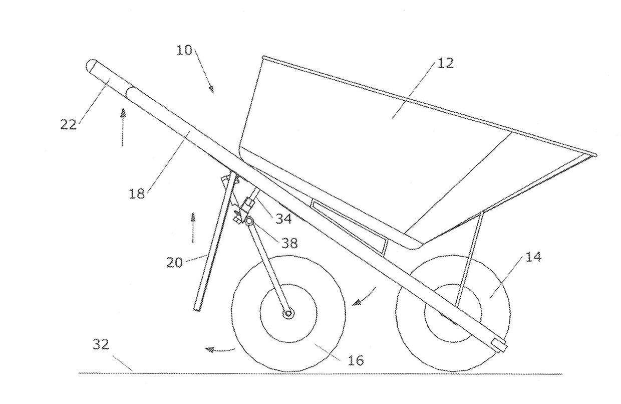
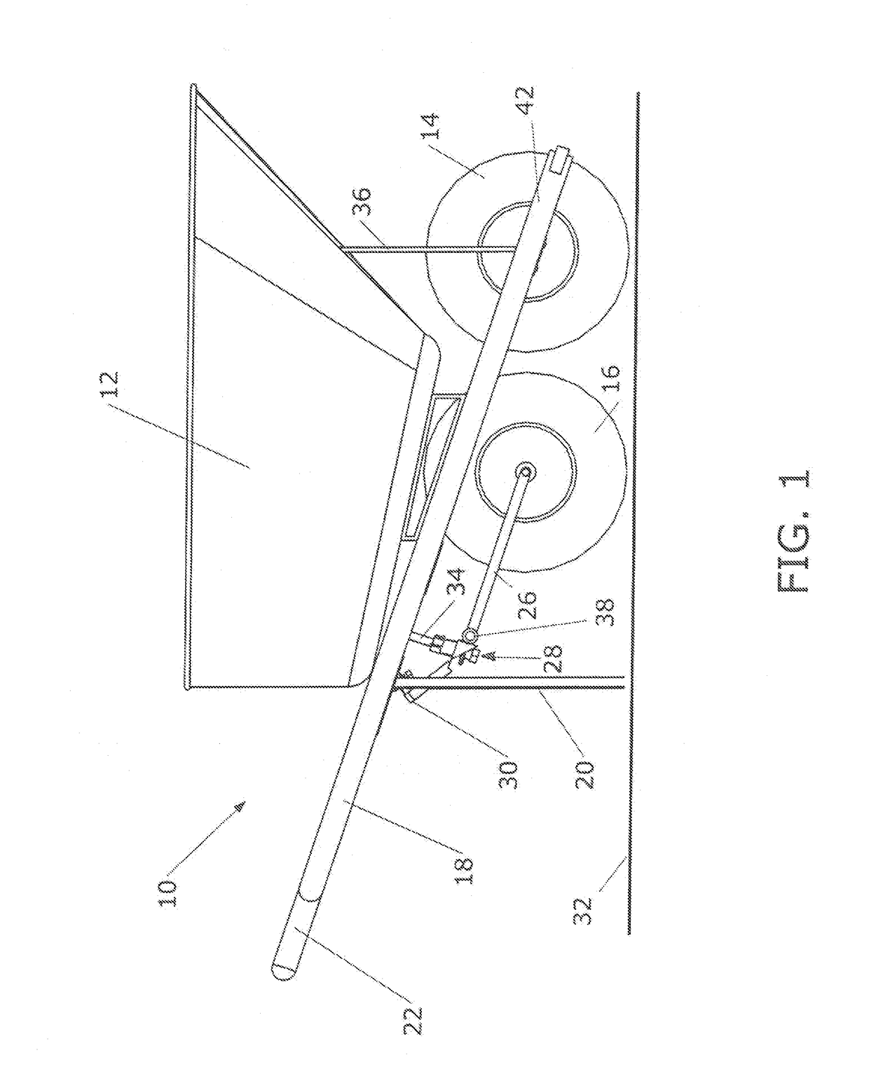
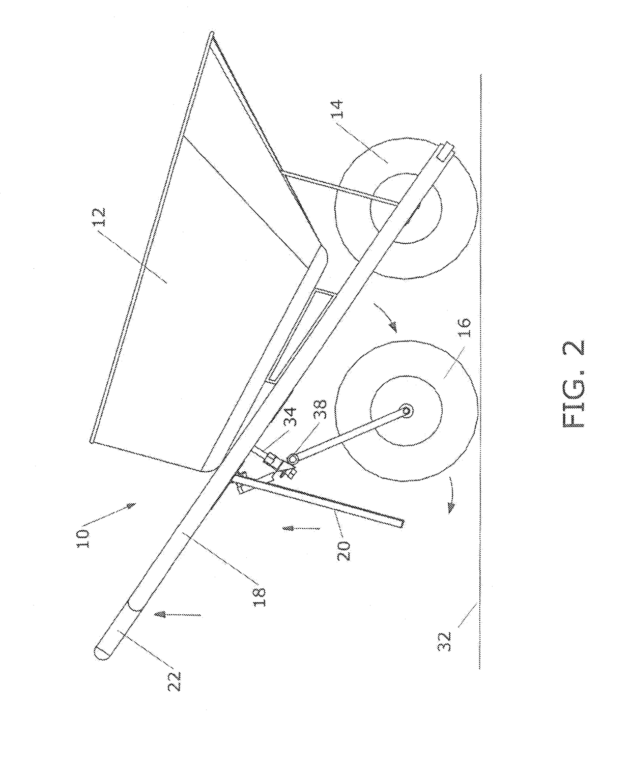
[0044]The present invention provides a wheelbarrow having an extendable wheel, which assists in supporting the weight of the load within the wheelbarrow. A preferred embodiment of the present invention is shown in FIG. 1. Wheelbarrow 10 comprises receptacle 12, front wheel 14, first handle 18, second handle 19 (not visible), legs 20, grip 22, front wheel fork 42, and receptacle support member 36. First and second handles 18, 19 have a first end and a second end. The first end of handles 18, 19 is located proximate grip 22, while the second end is located proximate front wheel 14. Optionally, crossbar 58 can connect first handle 18 to second handle 19 at second end. In this embodiment of the present invention, first and second handles 18, 19 and front wheel fork 42 are a single part. This is common with a typical prior art wheelbarrow. However, wheelbarrow 10 should not be limited to such a design. In other embodiments, front wheel fork 42 may be directly attached to receptacle 12 or...


PUM


Abstract

The present invention comprises a wheelbarrow for use on a surface. The wheelbarrow is generally comprised of a first and second handle, a receptacle, a chassis, at least one leg, a front wheel, a back wheel and an assembly. The assembly includes a on which allows back wheel to pivot between a first position and a second position. When the back wheel is in the first position, the legs are in contact with the surface. When the back wheel is in the second position the legs are raised off of the surface.

Description

CROSS-REFERENCES TO RELATED APPLICATIONS[0001]Not ApplicableSTATEMENT REGARDING FEDERALLY SPONSORED RESEARCH OR DEVELOPMENT[0002]Not ApplicableMICROFICHE APPENDIX[0003]Not ApplicableBACKSURFACE OF THE INVENTION[0004]1. Field of the Invention[0005]This invention relates to wheelbarrows. More specifically, the invention comprises a new wheelbarrow system for improving the maneuverability of a wheelbarrow.[0006]2. Description of the Related Art[0007]Wheelbarrows are often used in gardening and construction to carry heavy or bulky loads that would otherwise be difficult to carry without assistance. A wheelbarrow is generally a hand-propelled vehicle with only one wheel. It is generally comprised of a barrel, a front wheel, two legs and two handles. The wheelbarrow is able to distribute a load between a front wheel and the operator, when the operator lifts, by way of the handles, the legs off of the surface.[0008]Even with as distributed load, an operator still must bear a large portion ...

Claims


Application Information

Patent Timeline
IPC IPC(8): B62B1/20B62B1/18
CPCB62B1/208B62B1/186B62B2301/08B62B1/002B62B3/009B62B2301/10
Inventor LUNT, WARNER
Owner BEASTBARROW LLC
Features
  • Generate Ideas
  • Intellectual Property
  • Life Sciences
  • Materials
  • Tech Scout
  • Unparalleled Data Quality
  • Higher Quality Content
  • 60% Fewer Hallucinations
Learn More