
System for laser detection with enhanced field of view

a laser detection and enhanced field technology, applied in the direction of distance measurement, instruments, bundled fibre light guides, etc., can solve the problem of practically limiting the effective aperture of a given field of view

Active Publication Date: 2017-06-13
UNITED STATES OF AMERICA THE AS REPRESENTED BY THE SEC OF THE ARMY
View PDF9 Cites 7 Cited by
  • Summary
  • Abstract
  • Description
  • Claims
  • Application Information

AI Technical Summary

Benefits of technology

[0005]The light energy from each pulse is collected by the individual receive elements and combined by either electrically adding the signals or electrically switching the signals to form a composite receive pulse sampled by the ladar system. Since the light energy is paramount, optical distortion and aberrations do not severely affect the system performance. Also, by combining the individual receive elements together to form the composite field of view is performed electrically and does not require sophisticated algorithms or additional compute elements. Any imperfections, such as amplitude variations at the seams, can be characterized and normalized when the data is displayed to the user with no adverse effects. Due to these facts, this embodiment is distinguishable from applications that combine high fidelity imagery from separate focal plane array sensors or other imaging devices to form a larger composite image.
[0007]The ladar receiver performance is directly related to the effective aperture of the input optical system. Larger effective aperture increases the amount of light energy collected and increases the effective range of the system. However, the field of view of the optical system is inversely proportional to the effective aperture, practically limiting the size of the effective aperture for a given field of view. This embodiment solves this dilemma by dividing the overall field of view into smaller pieces, with each smaller piece covered by a separate receive element which can have a larger effective aperture due to its smaller field of view. Thus, when properly combined, the small field of view receivers increase the overall system performance over that which can be achieved with a single wide field of view receiver.
[0008]A preferred embodiment uses the enhanced capabilities described above for a Rotorcraft Advanced Surveillance and Collision Avoidance Ladar (RASCAL) application. Imaging laser radar (ladar) provide a 3-D image of the landing zone along with object size and distance from the aircraft information as a pilot aid for a rotary aircraft landing in these difficult situations. An ARL study demonstrated the preferred embodiment of the ladar is capable of satisfying the requirements for a landing zone imaging ladar. The ladar embodiment, originally designed for a PackBot, is very small and can easily be re-packaged into an existing rotorcraft internal compartment. No external pod mount is necessary, but may be optionally used.

Problems solved by technology

However, the field of view of the optical system is inversely proportional to the effective aperture, practically limiting the size of the effective aperture for a given field of view.

Method used


Image

  • System for laser detection with enhanced field of view
  • System for laser detection with enhanced field of view
  • System for laser detection with enhanced field of view

Examples


Embodiment Construction

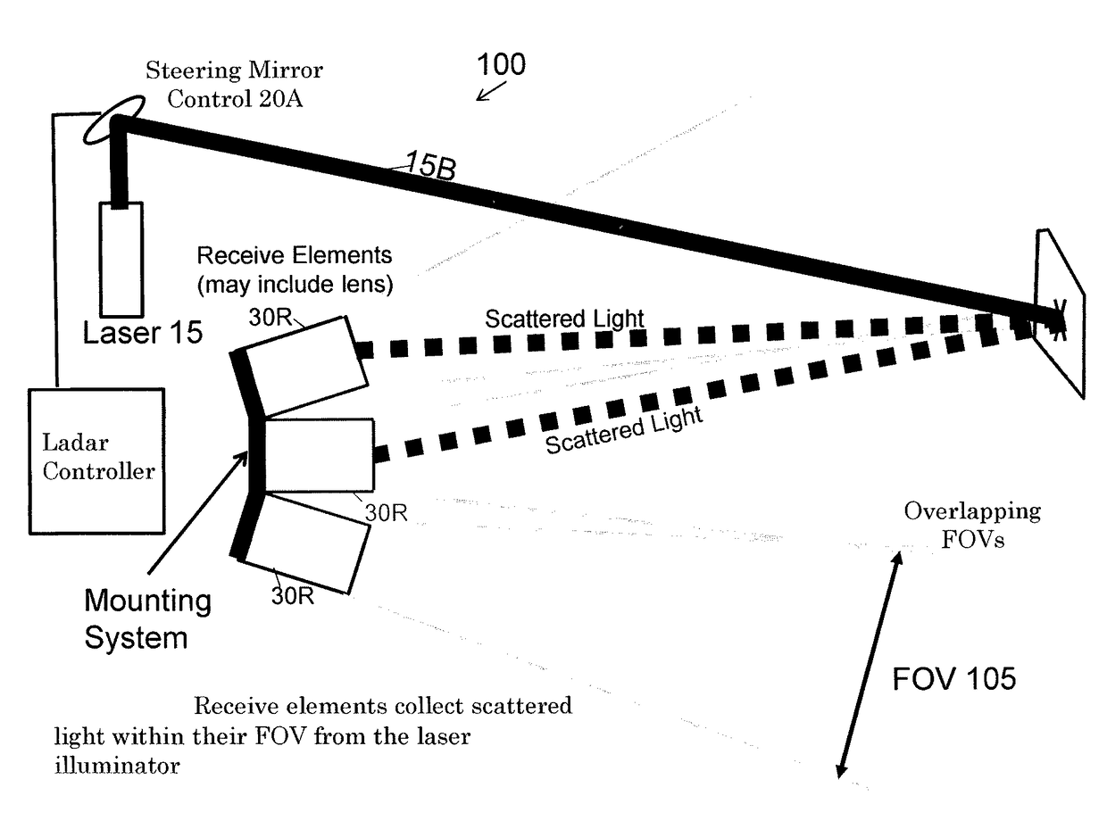
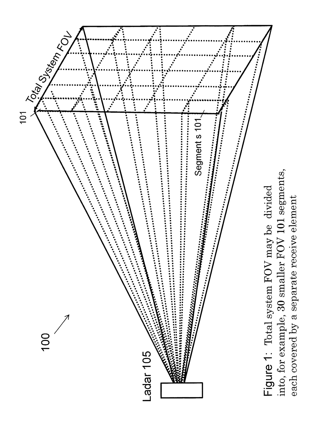
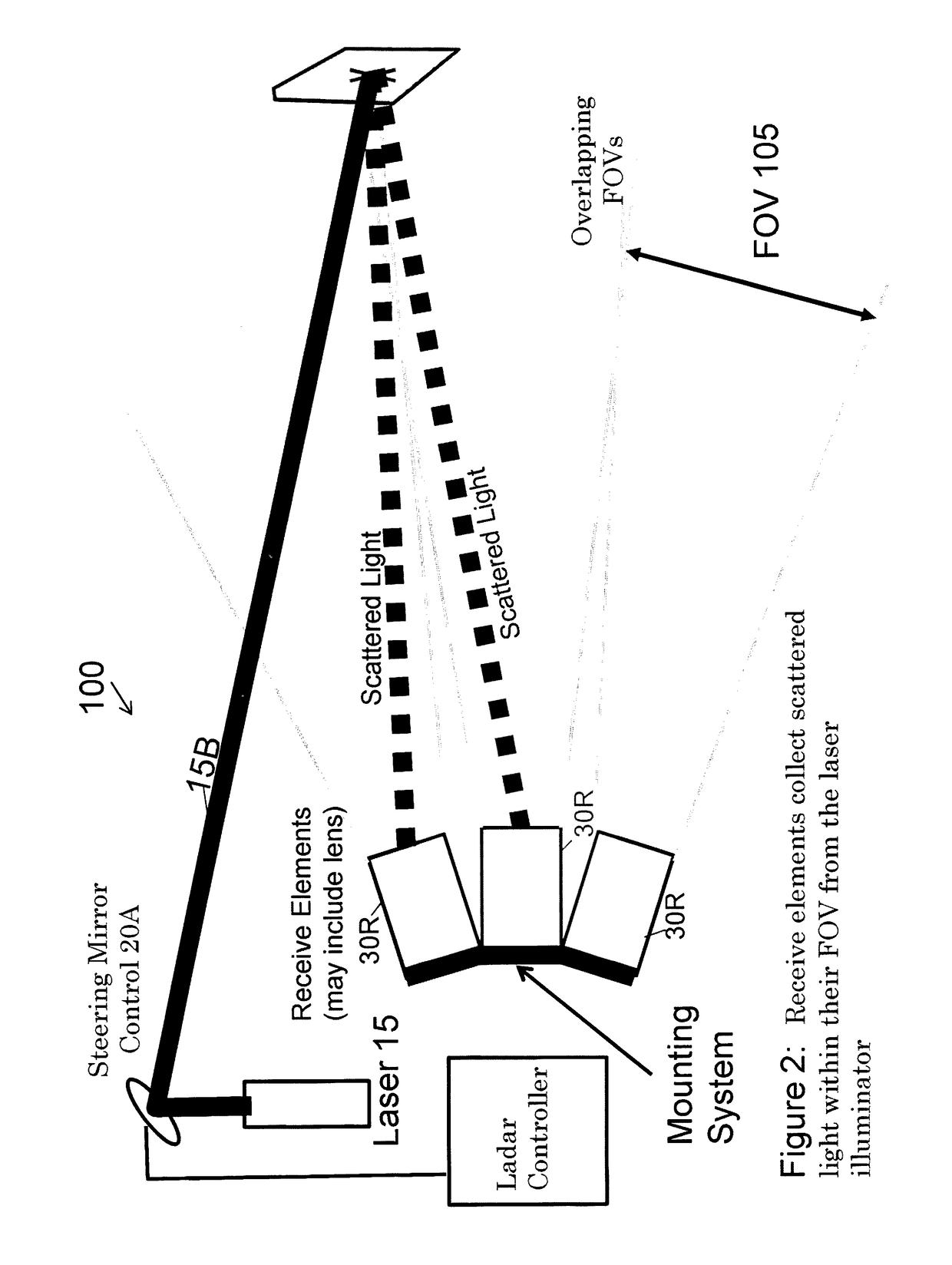
[0021]The embodiments of the invention and the various features and advantageous details thereof are explained more fully with reference to the non-limiting embodiments that are illustrated in the accompanying drawings and detailed in the following description. It should be noted that the features illustrated in the drawings are not necessarily drawn to scale. Descriptions of well-known components and processing techniques are omitted so as to not unnecessarily obscure the embodiments of the invention. The examples used herein are intended merely to facilitate an understanding of ways in which the embodiments of the invention may be practiced and to further enable those of skilled in the art to practice the embodiments of the invention. Accordingly, the examples should not be construed as limiting the scope of the embodiments of the invention.

[0022]The terminology used herein is for the purpose of describing particular embodiments only and is not intended to limit the full scope of ...


PUM


Abstract

A system comprising a laser for transmitting a beam of light towards a target area; a controller for controlling the output of the laser; a receiver for collecting reflected pulses of light reflected from the target area, the receiver comprising a plurality of receive elements, each of the receive elements having a different field of view; a combiner for combining the outputs of the receive elements into one composite signal of the target area; an interface circuitry for converting the composite signal into an image; display unit displaying output from interface circuitry.

Description

CROSS REFERENCE TO RELATED APPLICATIONS[0001]This application is a nonprovisional application of U.S. Provisional Application No. 61 / 700,631 to which priority is being claimed.STATEMENT OF GOVERNMENT INTEREST[0002]The invention described herein may be manufactured, used, and licensed by or for the United States Government.BACKGROUND OF THE INVENTION[0003]A LADAR transmitting and receiving system and method is disclosed in U.S. Pat. No. 8,081,301 (hereinafter '301 patent), hereby incorporated by reference. The '301 patent discloses a compact LADAR transmitting and receiving apparatus including a pulse laser generating pulses of light; a transmitter collimating and directing the pulses of light toward a target; a receiver collecting reflected pulses of light, the reflected pulses of light having been reflected from the target, the receiver comprising a tapered fiber bundle; a sensor operatively connected to the tapered fiber bundle, where the sensor comprises a photosensitive region a...

Claims


Application Information

Patent Timeline
Patent Type & Authority Patents(United States)
IPC IPC(8): G01C3/08G01S17/42G01S17/89G01S7/481G01S7/486G02B26/08G02B6/06G01S7/4861
CPCG01S17/89G01S7/4816G01S7/4861G01S17/42G02B6/06G02B26/0833
Inventor RUFF, WILLIAM CSTANN, BARRY LEEGIZA, MARK MLAWLER, WILLIAM B.
Owner UNITED STATES OF AMERICA THE AS REPRESENTED BY THE SEC OF THE ARMY
Learn More