
HUD system and method with dynamic light exclusion

a dynamic light exclusion and display technology, applied in the field of displays, can solve the problems of background saturation, loss of contrast ratio, and prone to loss of contrast ratio of displays

Active Publication Date: 2017-06-13
ROCKWELL COLLINS INC
View PDF554 Cites 68 Cited by
  • Summary
  • Abstract
  • Description
  • Claims
  • Application Information

AI Technical Summary

Benefits of technology

The patent describes a head up display (HUD) for use in an environment that can provide light from an image source. The HUD includes a sensor array, a combiner, and a dynamic gradient. The combiner allows viewing of both the outside scene and information from the image source. The dynamic gradient is a technology that can selectively reduce or prevent bright light from the outside environment from being transmitted through the combiner. This helps to create a more seamless and realistic view for the user.

Problems solved by technology

HUDs can be susceptible to a loss of contrast ratio in certain environmental conditions.
In substrate guided HUDs, the loss of contrast ratio can also be due to interference when the diffractive gratings in substrate waveguides are exposed to bright light.
Conventional uses of tinted lens and visors can reduce background saturation, but do not adequately solve lower contrast ratio issues.

Method used


Image

  • HUD system and method with dynamic light exclusion
  • HUD system and method with dynamic light exclusion
  • HUD system and method with dynamic light exclusion

Examples


Embodiment Construction

[0017]Before describing in detail the particular improved system and method, it should be observed that the invention includes, but is not limited to, a novel structural combination of optical components and not in the particular detailed configurations thereof. Accordingly, the structure, methods, functions, control and arrangement of components have been illustrated in the drawings by readily understandable block representations and schematic drawings, in order not to obscure the disclosure with structural details which will be readily apparent to those skilled in the art, having the benefit of the description herein. Further, the invention is not limited to the particular embodiments depicted in the exemplary diagrams, but should be construed in accordance with the language in the claims.

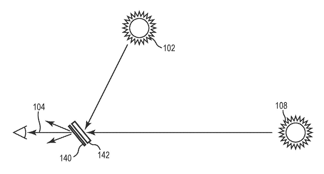
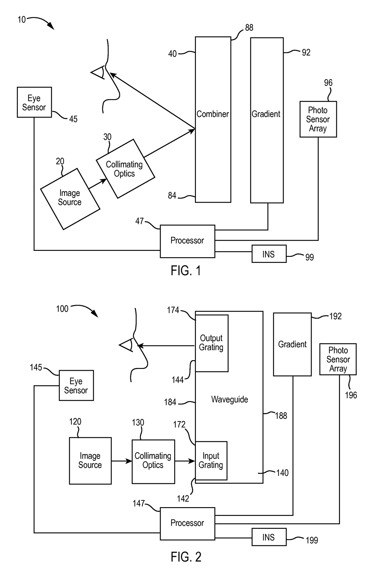
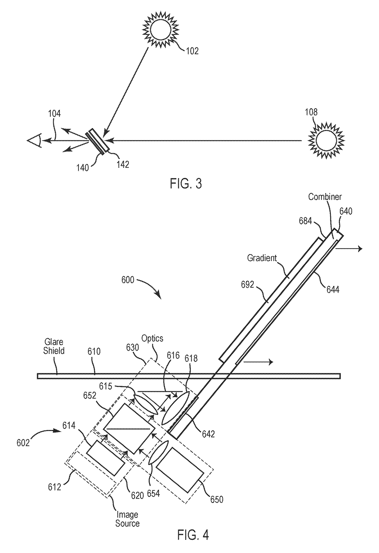
[0018]With reference to FIG. 1, a head up display (HUD) system 10 can be utilized in various applications, including but not limited to aviation, medical, naval, targeting, ground based, military...


PUM


Abstract

A system and method can mitigate or prevent contrast ratio issues due to bright light (e.g., light saturation) in a head up display (HUD). The head up display can include a waveguide combiner (or non-waveguide combiner) and a mitigator disposed to prevent or reduce bright light from being provided through the combiner. The bright light can be direct lunar light, direct solar light, or solar / lunar reflections. The mitigator dynamically selects and reduces bright background light which results in an increase of contrast ratio.

Description

CROSS REFERENCE TO RELATED APPLICATIONS[0001]The present application is related to: U.S. patent application Ser. No. 13 / 892,057, filed on May 10, 2013, by Stratton et al., and U.S. patent application Ser. No. 13 / 864,991, filed on Apr. 17, 2013 by Tiana et al., incorporated herein by reference herein in their entireties and assigned to the assignee of the present application.BACKGROUND OF THE INVENTION[0002]The present specification relates to displays. More particularly, the present specification relates to head up displays (HUDs).[0003]Conventional HUDs utilize an image source and a combiner to provide an image (e.g., symbology, enhanced vision, etc.) to a user. The user (e.g., a pilot) can view the image on the combiner as well as an environmental scene through the combiner. Substrate guided HUDs have been proposed which use waveguide combiners to preserve eye box size while reducing lens size. U.S. Pat. No. 4,309,070 issued to St. Leger Searle and U.S. Pat. No. 4,711,512 issued t...

Claims


Application Information

Patent Timeline
Patent Type & Authority Patents(United States)
IPC IPC(8): G06T5/00G02B27/01B60K35/00G06T5/20
CPCG06T5/008B60K35/00G02B27/01G06T5/20G02B5/23G02B27/0101G02B2027/0118H04N23/63B60K2360/20B60K2360/25B60K2360/21B60K2360/693B60K35/23B60K35/40B60K35/22H04N23/951G06T5/94
Inventor WALD, DANIEL S.WILSON, BRANDON E.STRATTON, ERIC P.KELLY, CONOR D.
Owner ROCKWELL COLLINS INC
Learn More