Valve block assembly for several valves

a valve block and valve technology, applied in the direction of valve housings, mechanical equipment, transportation and packaging, etc., can solve the problems of multiplicity of individual valves, inability to support lines alone, and impair the conductibility and efficiency of the heat pump system, so as to reduce the number of separation points and minimal impact on pressure losses

Active Publication Date: 2017-06-20
HANON SYST
View PDF17 Cites 2 Cited by
  • Summary
  • Abstract
  • Description
  • Claims
  • Application Information

AI Technical Summary

Benefits of technology

[0013]The object of the invention is therefore to devise a valve block assembly for multiple valves for fluid systems, in particular for refrigerant-conducting systems, which assembly decreases the number of separation points in the system of refrigerant lines and also has minimal impact on pressure losses on the refrigerant side.
[0014]A further object of the invention is to reduce the amount of refrigerant required by the system with regard to the component produced, and to likewise reduce the potential for oil retention and external refrigerant leakage.

Problems solved by technology

Due to the weight of the valves, however, they cannot be supported by the lines alone, and must instead be mounted in the vehicle by means of mounting fixtures.
The disadvantage of the submodule design is that a multiplicity of individual valves may have to be connected to other components, for example heat exchangers, by means of individual refrigerant lines within a very small space.
Due to the high complexity and the costs associated with this, the risk also exists that the complex line routes may allow oil traps to form in the submodule, and that increased pressure losses may impair the conductibility and efficiency of the heat pump system.
Moreover, in a heat pump system, due to the number of valves and connecting lines, the number of separating points and therefore the risk of external leakage is increased.
A further disadvantageous aspect is that, under certain circumstances, significant quantities of refrigerant may be stored in the inner volume of the connecting lines of the submodules.
This increases the volume of refrigerant required to operate the system and therefore also the costs.
This also gives rise to safety-relevant and environmentally relevant disadvantageous aspects.
One disadvantage of such embodiments is that, although valve blocks made of plastic can be relatively cost-effectively produced, their mechanical durability is frequently insufficient for mobile applications and for use at high pressures, such as those occurring in high-pressure refrigeration circuits.

Method used


Image

  • Valve block assembly for several valves
  • Valve block assembly for several valves
  • Valve block assembly for several valves

Examples


Embodiment Construction

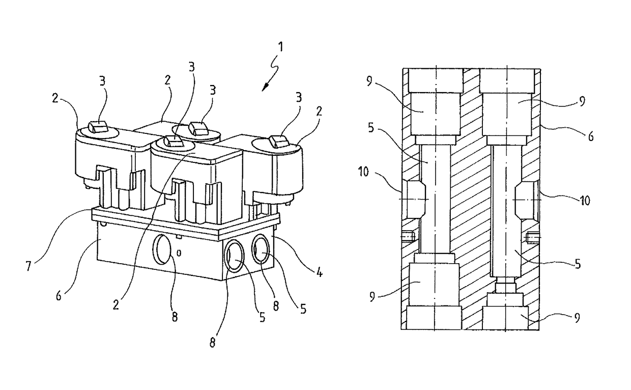
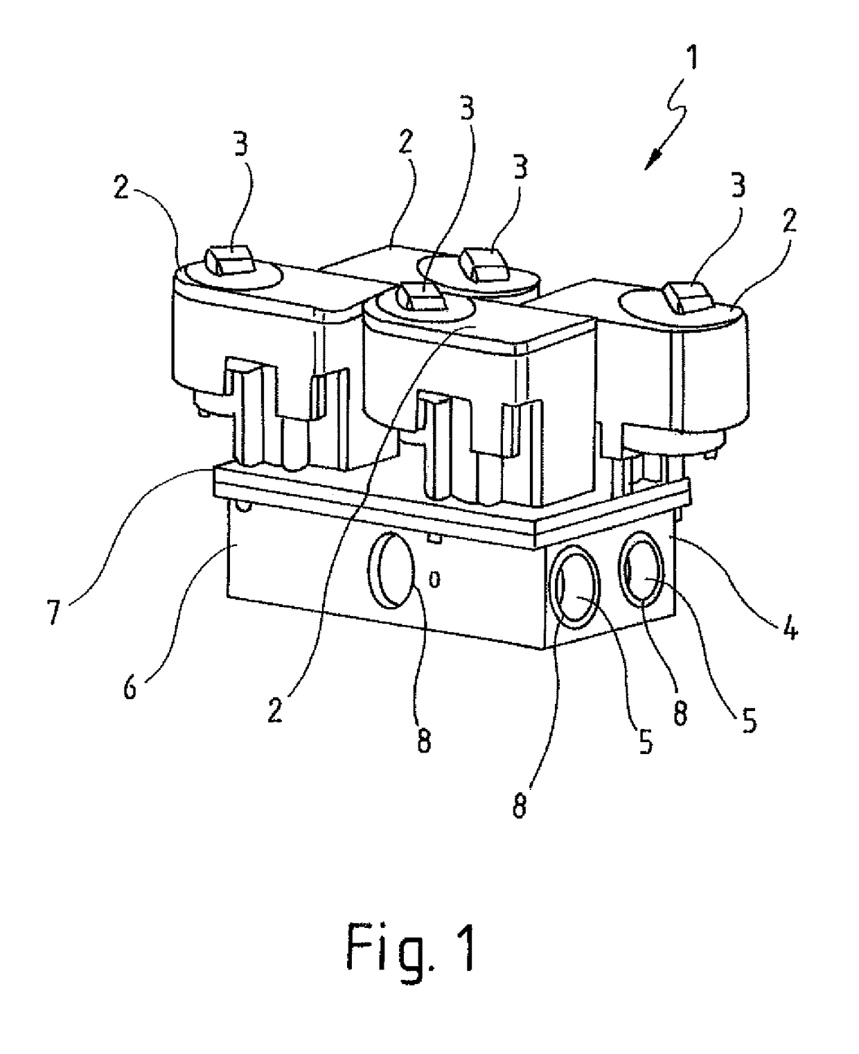
[0049]FIG. 1 shows a perspective view of a valve block assembly 1 comprising the main components of an adjustment unit 2, a drive unit 3 and a valve block 4. The valve block 4 is constructed in two parts comprising a flow path element 6 and a limiting element 7. The flow path element 6 contains flow paths 5 for the fluids, and fluid connections 8 for corresponding fluid lines with the associated connecting ports provided at the outer margins of the flow path element 6. The illustrated embodiment shows the basic structural design of the flow path element 6 as a rectangular block and of the limiting element 7 as a cover element, with the adjustment units 2 and the drive units 3 of the individual valves being represented and arranged on the limiting element 7.

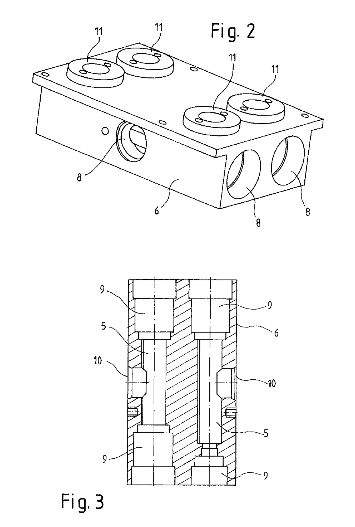
[0050]FIG. 2 shows a perspective view of the flow path element 6 as part of the valve block 4. The flow path element 6 comprises a plurality of flow paths 5 which emerge at the outer margins of the flow path element 6 as fluid con...


PUM


Abstract

A valve block assembly for multiple valves, in particular expansion valves and / or shut-off valves, includes a valve block having a plurality of flow paths for fluids and a plurality of adjustment units with assigned drive units, wherein the valve block is designed as comprising two parts, these being a flow path element with the flow paths and a limiting element.

Description

CROSS-REFERENCE TO RELATED APPLICATIONS[0001]This application claims priority to German Patent Application No. 10 2014 105097.5, filed on Apr. 10, 2014, the disclosure of which is incorporated herein by reference in its entirety.FIELD OF THE INVENTION[0002]The invention relates to a valve bock assembly for multiple valves, suitable particularly for use in combined refrigeration systems and heat pump systems of motor vehicles.BACKGROUND OF THE INVENTION[0003]Complex fluid system circuits are known in the prior art which involve various circuit options within the fluid system based on the functionalities that are required.[0004]For example, DE 10 2006 026 359 B4 describes an air conditioning system for vehicles which comprises a combined refrigeration system and heat pump system. Additional applications for generic valve block assemblies include refrigeration systems according to DE 10 2010 042 127 A1 and DE 10 2012 111 672 A1.[0005]In the aforementioned complex circuit systems accord...

Claims


Application Information

Patent Timeline
Patent Type & Authority Patents(United States)
IPC IPC(8): F16K27/00F15B13/08
CPCF16K27/003F15B13/0814Y10T137/87153Y10T137/87249Y10T137/87885F16K27/00B60H1/32
Inventor LE PELLEC, CORINNEGRAAF, MARC
Owner HANON SYST
Why Eureka
Try Eureka