Positioning device for horizontal external ignition apparatus

a positioning device and ignition apparatus technology, applied in the direction of electrical apparatus, lighting and heating apparatus, combustion process, etc., can solve the problems of inconvenient installation, assembly and disassembly, complex structure of conventional positioning devices, etc., and achieve the effect of convenient installation, simple structure and excellent

Active Publication Date: 2017-06-20
BEIJING NAURA MICROELECTRONICS EQUIP CO LTD
View PDF2 Cites 0 Cited by
  • Summary
  • Abstract
  • Description
  • Claims
  • Application Information

AI Technical Summary

Benefits of technology

[0010]In one embodiment, the lifting module includes a height limit member; the height limit member includes a long slot block having a longitudinal long slot and a round hole block having a round hole provided respectively on the mounting member and the lifting base. An inserting member moves up and down in the longitudinal long slot by penetrating the longitudinal long slot and inserting into the round hole, so as to limit the adjustable range of the distance between the mounting member and the lifting base to the length of the longitudinal long slot.
[0018]Accordingly, the positioning device of the horizontal external ignition apparatus of the present invention can adjust the rotating angle, the lateral movement, and the longitudinal movement of the external ignition chamber by the rotating module, the expansion module, and the lifting module to position the external ignition chamber with excellent effect. Furthermore, the positioning device is simple in structure and convenient in installation, and is enabled to adjust the rotating angle to horizontally extract the external ignition chamber in order to satisfy the requirements for the assembly and disassembly of the external ignition chamber.

Problems solved by technology

However, the conventional positioning device is complex in structure and inconvenient in installation, assembly and disassembly.

Method used


Image

  • Positioning device for horizontal external ignition apparatus
  • Positioning device for horizontal external ignition apparatus
  • Positioning device for horizontal external ignition apparatus

Examples


first embodiment

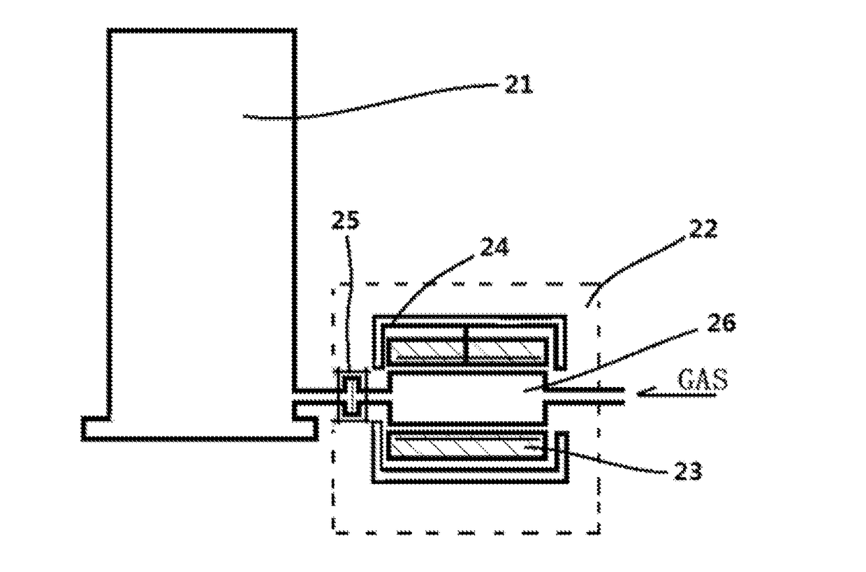
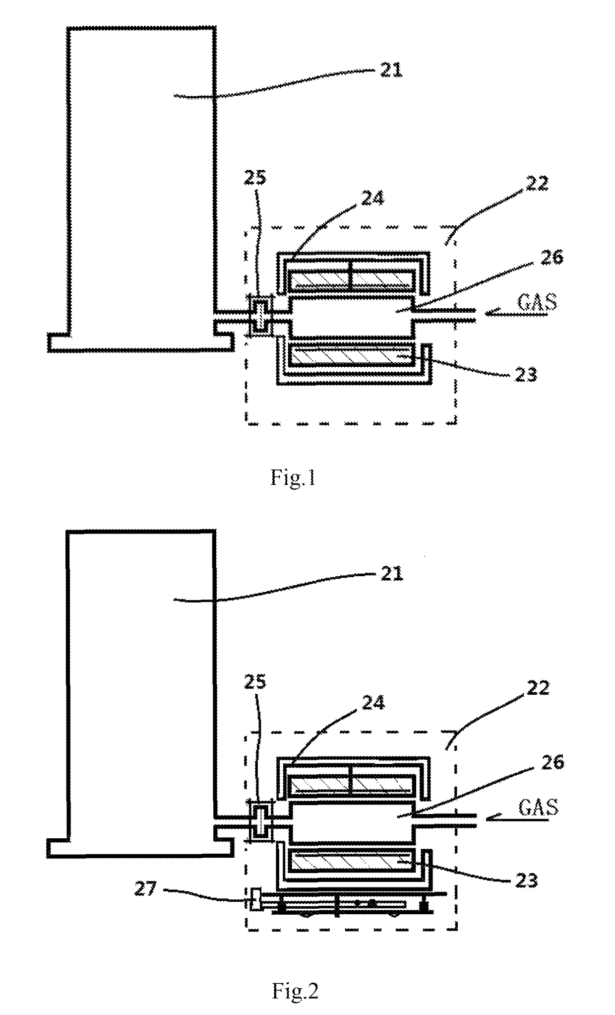
[0029]Referring to FIG. 2, the positioning device 27 of the present embodiment is installed at the bottom of the water cooling device 24 of the horizontal external ignition apparatus 22.

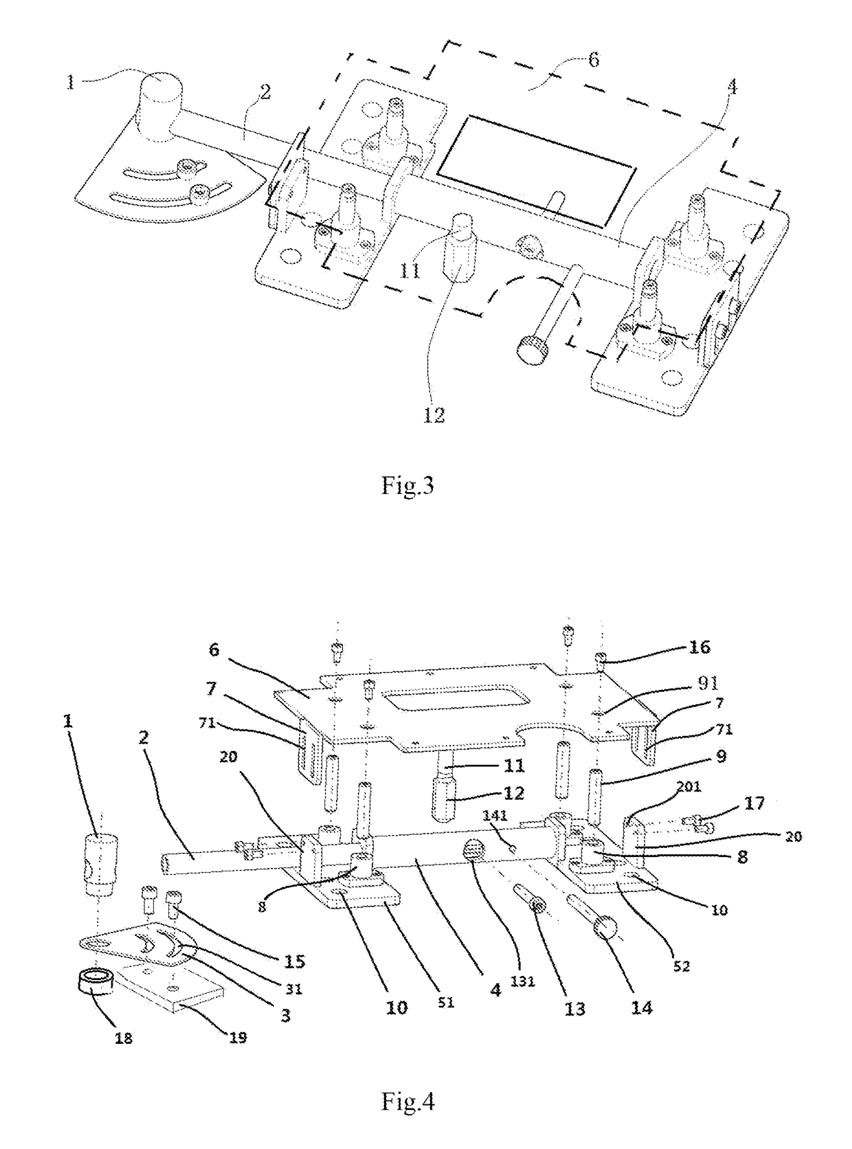
[0030]Referring to FIG. 2, FIG. 3 and FIG. 5, the positioning device 27 of the horizontal external ignition apparatus of the present embodiment includes a mounting plate 6 (the mounting member) and an adjusting component. The mounting plate 6 is fixed to the water cooling device 24 of the external ignition apparatus. A cylindrical heating device 23 is fixed in the cylindrical water cooling device 24 and the external ignition chamber 26 is fixed in the cylindrical heating device 23, therefore the mounting plate 6 is fixed to the external ignition chamber 26.

[0031]The adjusting component includes: a rotating module, an expansion module and a lifting module.

[0032]The rotating module includes a spindle sleeve 18 and a spindle member 1. The spindle sleeve 18 is fixed at the bottom of the external ignition...


PUM


Abstract

The invention discloses a positioning device for a horizontal external ignition apparatus. The positioning device comprises a rotating module, an expansion module, a lifting module, and a mounting member fixed at the bottom of a water cooling device of the ignition apparatus. The rotating module drives the mounting member and the external ignition chamber of the ignition apparatus to rotate around the spindle member of the rotating module and adjust the rotation angle. The expansion module adjust the lateral movement of the mounting member and the external ignition chamber along the expansion member of the expansion module. The lifting module adjust the longitudinal movement of the mounting member and the external ignition chamber.

Description

CROSS-REFERENCES TO RELATED APPLICATIONS[0001]This application claims the priority of Chinese patent application number 201410174582.5, filed on Apr. 28, 2014, the entire contents of which are incorporated herein by reference.FIELD OF THE INVENTION[0002]The present invention relates to the field of semiconductor manufacturing device, and more particularly to a positioning device for a horizontal external ignition apparatus of a heat treatment apparatus.BACKGROUND OF THE INVENTION[0003]In a vertical semiconductor heat treatment apparatus, an external ignition apparatus is connected to the process chamber of the heat treatment apparatus. The external ignition apparatus comprises an ignition chamber connected to the process chamber through a transition tube, a heating device to heat the process gas and perform a certain reaction, and a gas intake tube to introduce the heated process gas into the process chamber.[0004]FIG. 1 is a view illustrating the connection between a vertical proce...

Claims


Application Information

Patent Timeline
Patent Type & Authority Patents(United States)
IPC IPC(8): F23Q13/00H01L21/00H01L21/67
CPCH01L21/00H01L21/67017H01L21/67109
Inventor TAN, RUILEIDONG, JINWEI
Owner BEIJING NAURA MICROELECTRONICS EQUIP CO LTD
Why Eureka
Try Eureka