Threshing apparatus in a combine harvester having a multiposition stop device for setting clearance of concave grate segment

a technology of concave grate and threshing apparatus, which is applied in the field of concave adjustment mechanism of threshing apparatus of combine harvester, can solve the problem of increasing and achieve the effect of limiting the adjustment range of the concave frame and the lower limit of the adjustment rang

Inactive Publication Date: 2019-09-10
AGCO CORP
View PDF28 Cites 1 Cited by
  • Summary
  • Abstract
  • Description
  • Claims
  • Application Information

AI Technical Summary

Benefits of technology

[0016]The stop element, in one or more positions, serves to limit the adjustment range of the concave frame by contacting a part of the main frame for example. The position of the stop element can be influenced by the design of a concave grate segment installed in the grate reception zone. For example, in one embodiment, the installed concave grate segment has a profile which forces the stop element outside of the grate reception zone and, as a result, increases the lower limit of the adjustment range. In another embodiment, the installed concave grate segment has a profile which permits the stop element to reside inside the grate reception zone.

Problems solved by technology

For example, in one embodiment, the installed concave grate segment has a profile which forces the stop element outside of the grate reception zone and, as a result, increases the lower limit of the adjustment range.

Method used


Image

  • Threshing apparatus in a combine harvester having a multiposition stop device for setting clearance of concave grate segment
  • Threshing apparatus in a combine harvester having a multiposition stop device for setting clearance of concave grate segment
  • Threshing apparatus in a combine harvester having a multiposition stop device for setting clearance of concave grate segment

Examples


first embodiment

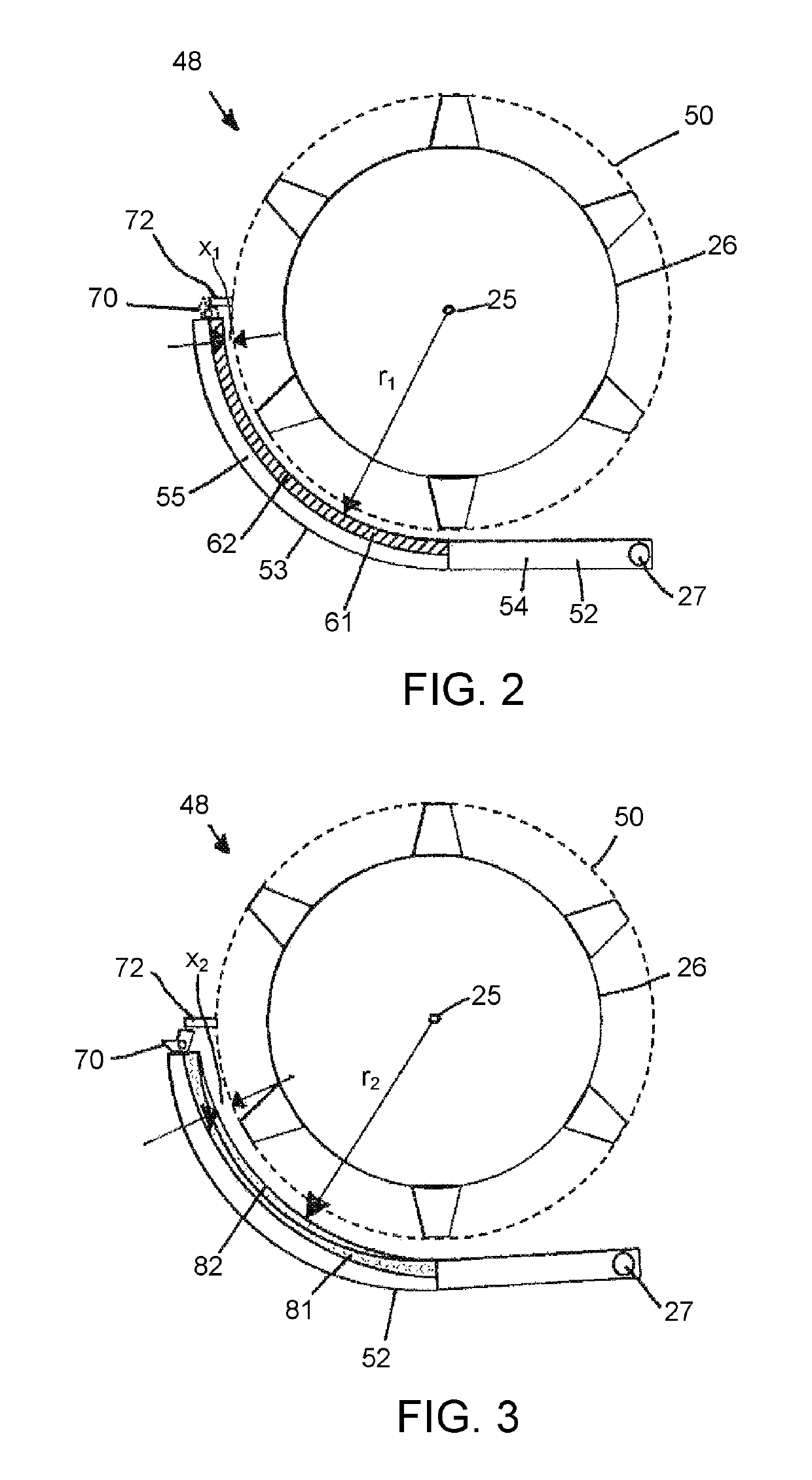
[0043]With reference to FIG. 2, threshing apparatus 48 in accordance with the invention comprises a threshing rotor 26 which is operable to rotate on a rotation axis 25 and define a substantially cylindrical swept envelope 50 when in rotation. A concave frame 52 comprises an arcuate portion 53 and a straight portion 54, the arcuate portion 53 being adapted to support a set of concave grate segments in a grate reception zone 55.

[0044]The concave frame 52 is pivotally mounted to a main vehicle frame for movement around a pivot axis 27 which is parallel to the rotor axis 25. The pivoting movement of the concave frame 52 enables adjustment of a radial clearance ‘x1’ between the swept envelope 50 and the supported grate segments. An adjustment linkage (not shown in FIG. 2) is coupled to the concave frame for adjusting the radial clearance x1 within an adjustment range. The clearance x may be adjusted manually by the operator or automatically by an electronic control system.

[0045]As expla...

second embodiment

[0051]FIGS. 5-12 illustrate the invention in more detail. However, it should be appreciated that the threshing apparatus described operates in much the same way as that described above.

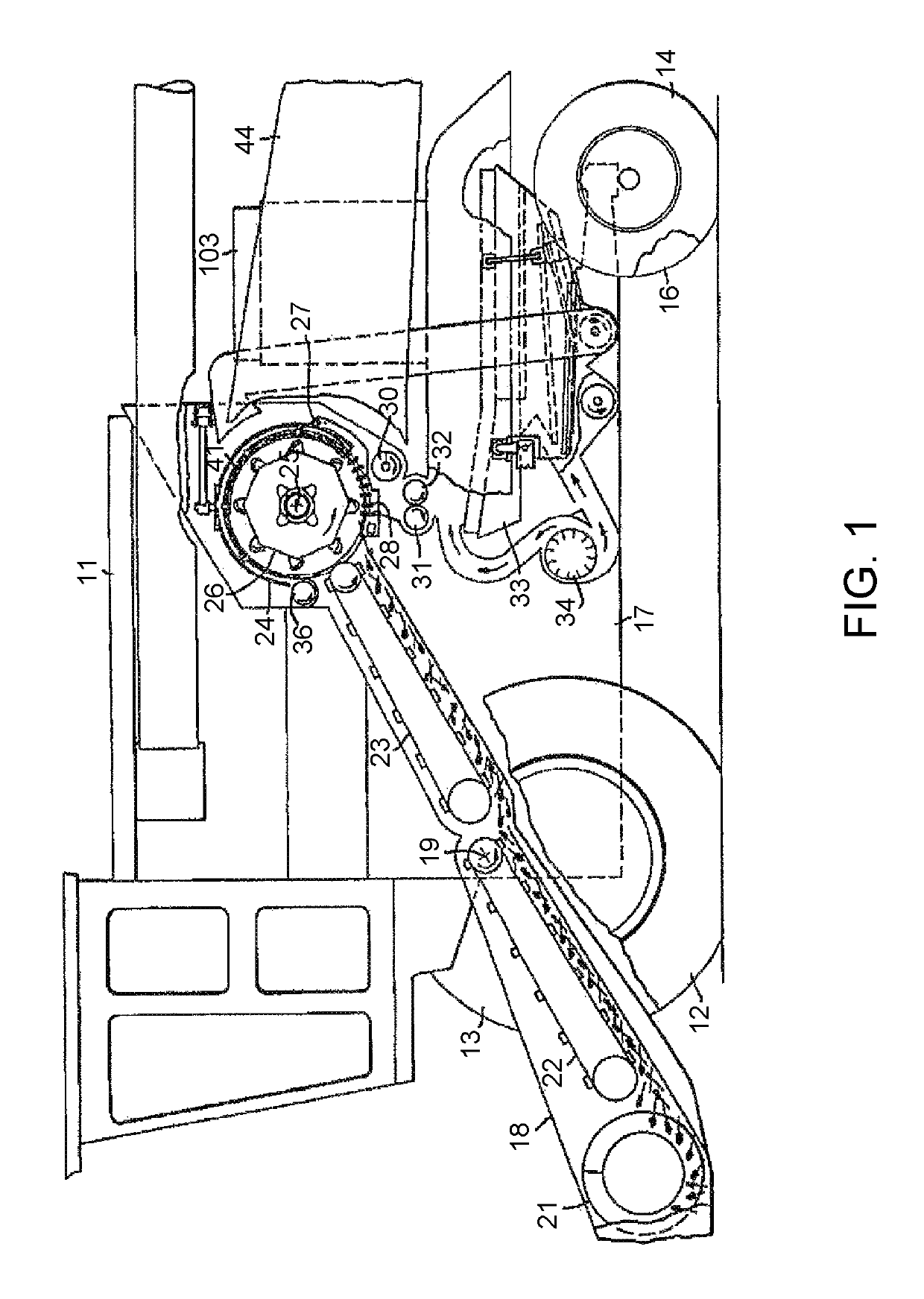
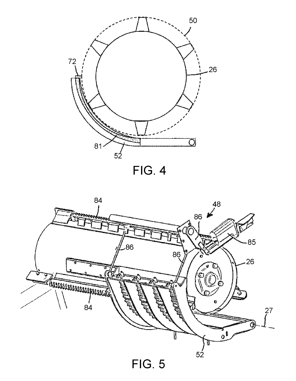
[0052]With reference to FIG. 5, threshing apparatus 48 comprises a main frame 17 and a threshing rotor 26 supported for rotation. Threshing elements in the form or rasp bars 84 are secured to the outside of the rotor 26.

[0053]A concave frame 52 is pivotally mounted to the frame 17 around a pivot axis 27. A concave adjustment system comprises a linear actuator 85 mounted to the main frame 17. The linear actuator 85 is coupled to the concave frame 52 by an adjustment linkage 86, together being operable to adjust the radial clearance of the concave within an adjustment range by pivoting the concave frame 52 around the pivot axis 27. The concave adjustment system is known in the art and alternative arrangements to that illustrated will be within the realms of normal workshop practice.

[0054]Turning to FIG....


PUM


Abstract

A threshing apparatus in a combine harvester has a main frame and a threshing rotor supported by the main frame. A concave frame supports one or more interchangeable arcuate concave grate segments in a grate reception zone. An adjustment mechanism provides adjustment of clearance between the concave grate segments and the rotor. A multi-position stop device is provided to determine the lower limit of a concave adjustment range. The position of the stop device is determined by a profile of an installed one of the interchangeable concave grate segments.

Description

BACKGROUND OF THE INVENTION[0001]Field of the Invention[0002]The invention relates to a concave adjustment mechanism in threshing apparatus of a combine harvester, and in particular to threshing apparatus that can accept different concave grate segments for harvesting different crops.[0003]Description of Related Art[0004]Agricultural combines are large machines that harvest, thresh, separate and clean an agricultural crop. The resulting clean grain is stored in a grain tank located on the combine. The clean grain can then be transported from the grain tank to a truck, grain cart or other receiving bin by an unloading auger. In a rotary processing system the crop travels axially parallel to and helically around the rotational axis of one or more rotary processing devices commonly referred to as rotors. In conventional, or tangential-flow, systems, during at least a portion of its travel through the system the crop travels in a transverse or tangential direction relative to the rotati...

Claims


Application Information

Patent Timeline
Patent Type & Authority Patents(United States)
IPC IPC(8): A01F12/28A01F12/20A01F12/26A01F7/06
CPCA01F12/28A01F12/26A01F12/20A01F7/06
Inventor REGIER, BERNARD D.
Owner AGCO CORP
Why Eureka
Try Eureka