Method of dividing plate-shaped workpieces

a technology of workpieces and plates, applied in the direction of soldering apparatus, semiconductor/solid-state device testing/measurement, auxilary welding devices, etc., can solve the problems of large expenditure of labor and time for gluing plate-shaped workpieces to adhesive sheets, and achieve the effect of efficiently and highly accurate dividing of device chips

Active Publication Date: 2017-06-20
DISCO CORP
View PDF9 Cites 0 Cited by
  • Summary
  • Abstract
  • Description
  • Claims
  • Application Information

AI Technical Summary

Benefits of technology

[0007]It is therefore an object of the present invention to provide a method of dividing a plate-shaped workpiece into device chips efficiently and highly accurately.
[0009]The method according to the present invention allows the plate-shaped workpieces to be divided into device chips efficiently and highly accurately.

Problems solved by technology

However, according to the technology disclosed in Japanese Patent Laid-Open No. 2003-086542, since the plate-shaped workpieces need to be stuck to the adhesive sheet in highly accurately aligned arrays, it requires a large expenditure of labor and time to stick the plate-shaped workpieces to the adhesive sheet.

Method used


Image

  • Method of dividing plate-shaped workpieces
  • Method of dividing plate-shaped workpieces
  • Method of dividing plate-shaped workpieces

Examples


first embodiment

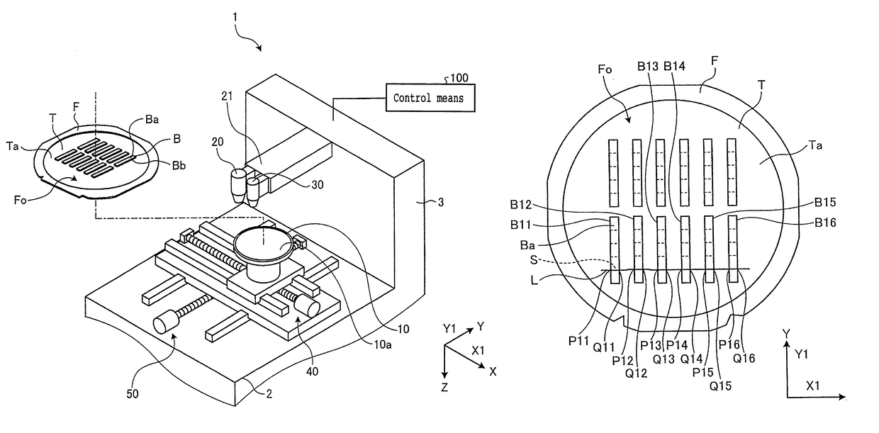
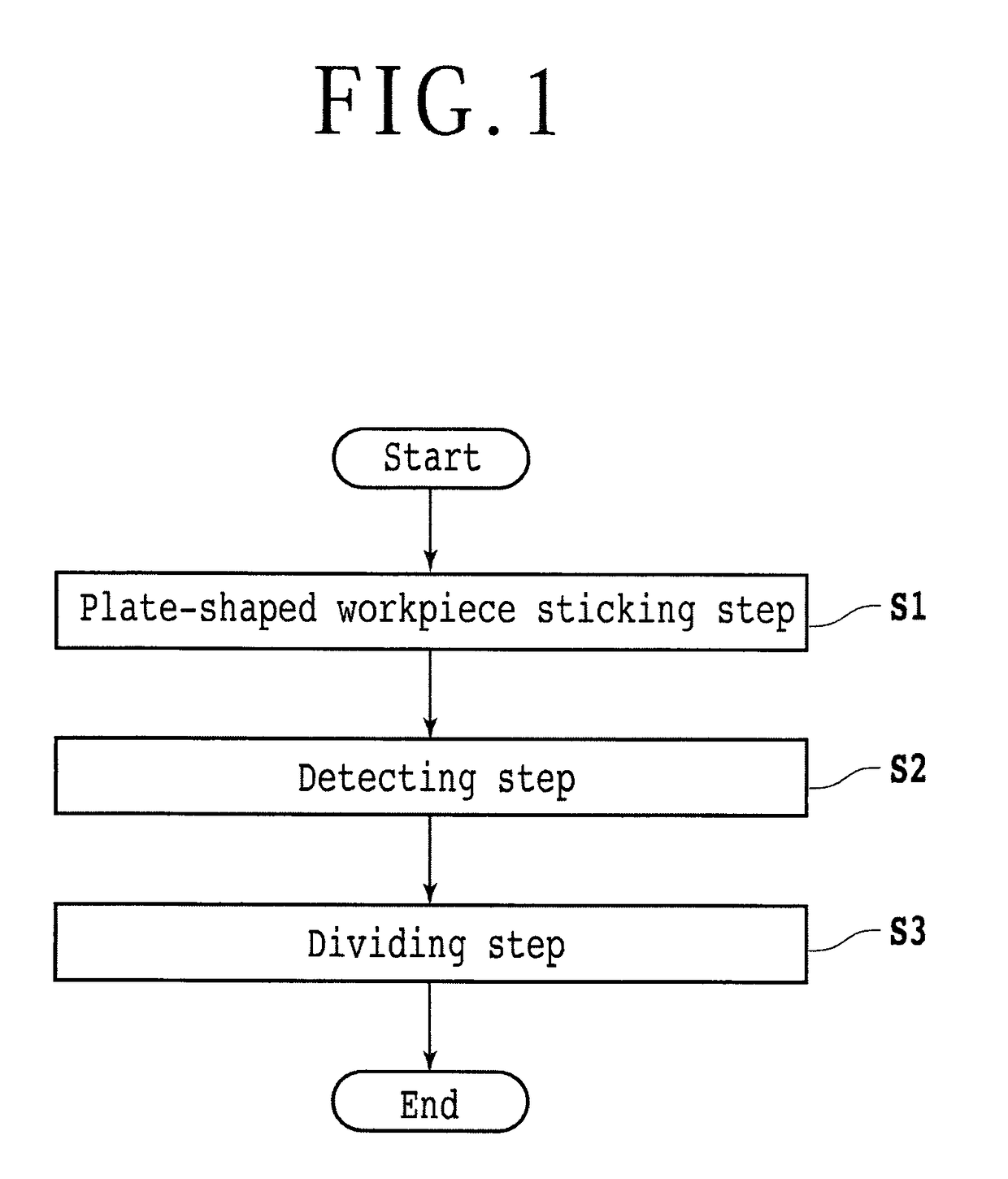
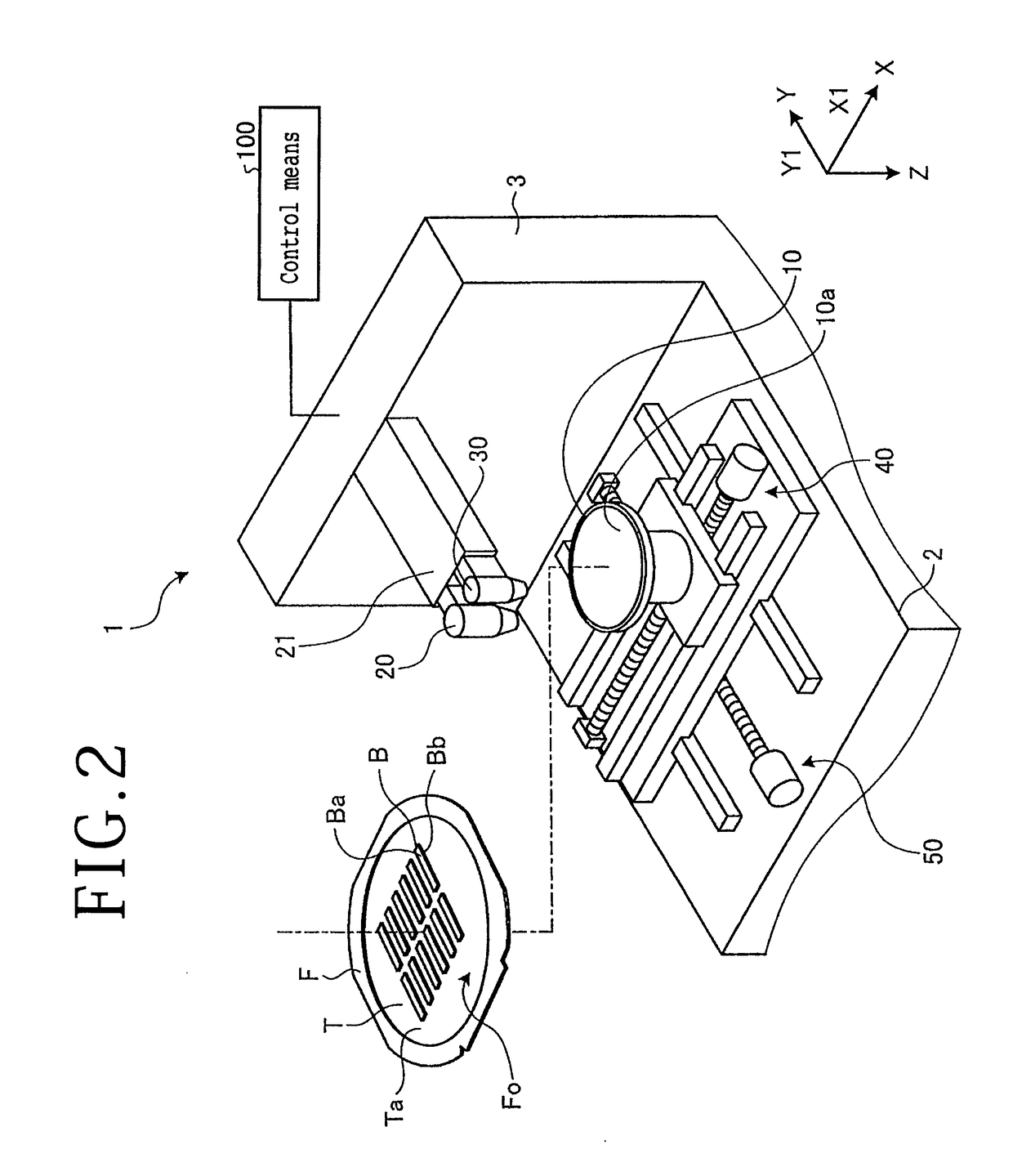
[0017]FIG. 1 is a flowchart of a dividing method according to a first embodiment of the present invention. FIG. 2 is a perspective view of a laser processing apparatus for carrying out the dividing method according to the first embodiment. FIG. 3 is a plan view of plate-shaped workpieces to be divided by the dividing method according to the first embodiment. FIG. 4 is an enlarged fragmentary plan view of some of the plate-shaped workpieces depicted in FIG. 3.

[0018]In the dividing method according to the first embodiment, a laser processing apparatus 1 applies a laser beam to plate-shaped workpieces B to divide them. As depicted in FIG. 1, the dividing method includes a plate-shaped workpiece sticking step S1, a detecting step S2, and a dividing step S3 which are successively carried out in the order named. According to the present embodiment, the plate-shaped workpieces B are stuck to an annular frame F in the plate-shaped workpiece sticking step S1. The positions and angles of proj...

second embodiment

[0038]A second embodiment of the present invention will be described below. The second embodiment is concerned with another aspect of a detecting step S2 and a dividing step S3. According to the second embodiment, the detecting step S2 and the dividing step S3 are carried out for each laser processing line L.

[0039]In the dividing method according to the present embodiment, after the plate-shaped workpiece sticking step S1 has been performed, for each of the laser processing lines L, the positions and angles of the projected dicing lines S on each plate-shaped workpiece B are detected in the detecting step S2, and the plate-shaped workpieces B are divided into a plurality of devices D along the projected dicing lines S in the dividing step S3. More specifically, after the plate-shaped workpiece sticking step S1 has been performed, the laser processing apparatus 1 detects the first projected dicing line S along the Y-axis directions in the detecting step S2 and divides the plate-shape...


PUM

PropertyMeasurementUnit
speedaaaaaaaaaa
distanceaaaaaaaaaa
distancesaaaaaaaaaa

Abstract

Disclosed herein is a method of dividing rectangular plate-shaped workpieces into individual device chips including a detecting step wherein an annular frame to which a plurality of rectangular plate-shaped workpieces are stuck is held on a chuck table and the positions and angles of the projected dicing lines on each of the plate-shaped workpieces are detected, and a dividing step wherein a laser beam having a wavelength which is absorbable by the plate-shaped workpieces is applied from a laser beam applying unit to the plate-shaped workpieces while the chuck table and the laser beam applying unit are being relatively processing-fed and finely adjusted for each of the plate-shaped workpieces on the basis of the positions and angles detected in the detecting step, thereby dividing the plate-shaped workpieces into a plurality of device chips along the projected dicing lines.

Description

BACKGROUND OF THE INVENTION[0001]Field of the Invention[0002]The present invention relates to a method of dividing plate-shaped workpieces.[0003]Description of the Related Art[0004]In the step of fabricating devices including semiconductor devices and optical devices, a grid of projected dicing lines is formed on the surface of a wafer to demarcate it into a plurality of areas, and semiconductor devices including integrated circuits (ICs) and large scale integration (LSI) circuits or optical devices including light-emitting diodes and laser diodes are formed in the demarcated areas. Thereafter, the wafer with the devices formed thereon is divided into device chips along the projected dicing lines. Japanese Patent Laid-Open No. 2003-086542 discloses, in the step of dividing the wafer, a method of cleaving the wafer into a plurality of rectangular plate-shaped workpieces each including a plurality of devices and, after an end face protective film is formed on the cleaved faces, dividi...

Claims


Application Information

Patent Timeline
Patent Type & Authority Patents(United States)
IPC IPC(8): H01L21/78B23K26/38B23K26/03B23K26/08H01L21/66B23K101/40B23K103/00
CPCH01L21/78B23K26/032B23K26/0853B23K26/38H01L22/12B23K2201/40B23K2203/56B23K37/0235B23K37/0408B23K26/0823B23K26/402H01L33/0095B23K2101/42B23K2103/50B23K2101/40B23K2103/56
Inventor YOSHIKAWA, TOSHIYUKISAMPEI, TAKASHI
Owner DISCO CORP
Why Eureka
Try Eureka