Microscope illumination apparatus, microscope, and microscope illumination method

a technology of illumination apparatus and microscope, which is applied in the direction of microscopes, instruments, optics, etc., can solve the problems of heat damage to the liquid-immersion objective lens, the energy density of the laser light at this back focal position becomes extremely high, and the information bias to be obtained

Active Publication Date: 2017-06-27
EVIDENT CORP
View PDF19 Cites 4 Cited by
  • Summary
  • Abstract
  • Description
  • Claims
  • Application Information

AI Technical Summary

Problems solved by technology

Although this is a general microscopy method that allows high-contrast observation of a specimen in an extremely thin region in the immediate vicinity of the surface of the cover glass, there is a problem in that total reflection illumination, with which illumination is provided from one direction, only allows biased fluorescence information to be obtained.
In the case in which the NA is increased for laser light that is made incident at the back focal position of the liquid-immersion objective lens in order to increase the viewing field area, the energy density of the laser light at this back focal position becomes extremely high, and the liquid-immersion objective lens is damaged by heat.
Furthermore, because it is necessary to perform time averaging, high-speed image acquisition is not possible, and thus, the imaging subject shifts due to vibrations of a galvanometer mirror, a motor, or the like.

Method used


Image

  • Microscope illumination apparatus, microscope, and microscope illumination method
  • Microscope illumination apparatus, microscope, and microscope illumination method
  • Microscope illumination apparatus, microscope, and microscope illumination method

Examples


first embodiment

[0026]A microscope illumination apparatus 4, a microscope 1, and a microscope illumination method according to a first embodiment of the present invention will be described below with reference to FIGS. 1 to 6.

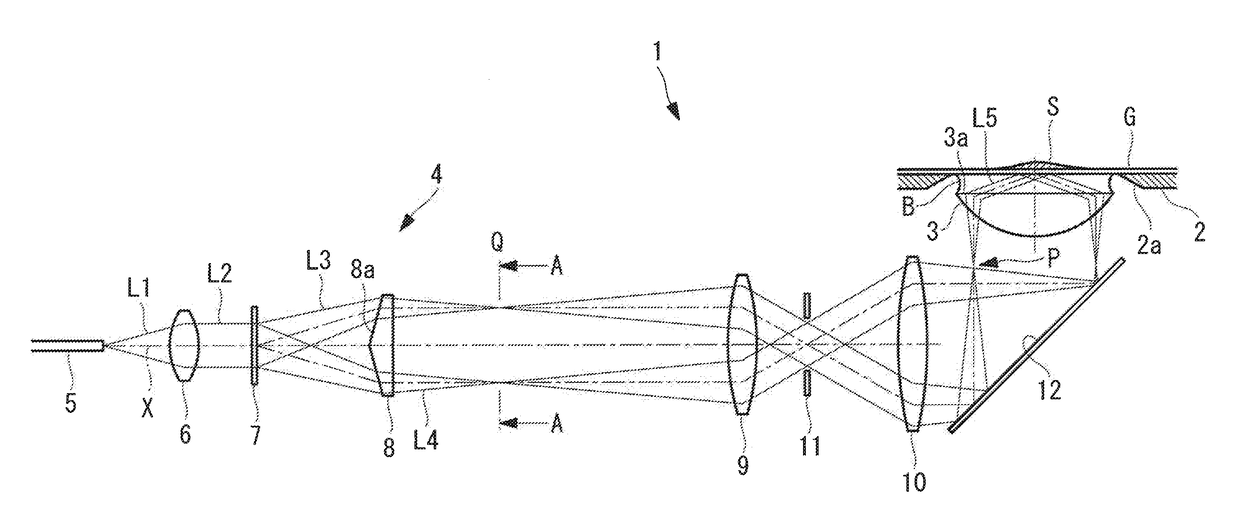
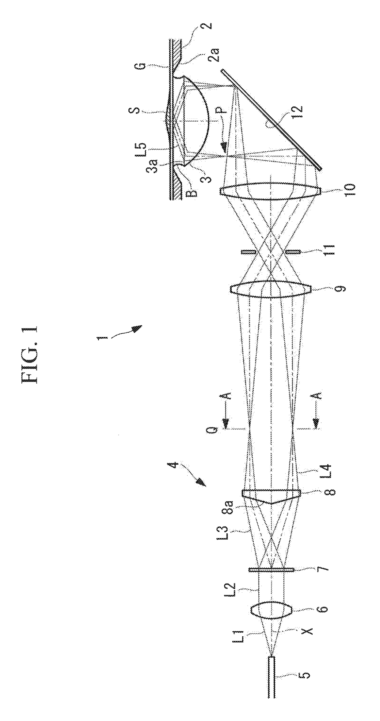
[0027]As shown in FIG. 1, the microscope 1 according to this embodiment is provided with a stage 2 on which a specimen S is placed, a liquid-immersion objective lens (focusing lens) 3 that is disposed below the stage 2 so as to point upward in the vicinity of the stage 2, and the microscope illumination apparatus 4 that radiates laser light onto the specimen S via the liquid-immersion objective lens 3.

[0028]The specimen S is placed on the stage 2 once mounted on a cover glass G. An opening 2a is provided in the stage 2, and the laser light focused by the liquid-immersion objective lens 3 is radiated onto the specimen S from below via the opening 2a and through the cover glass G on the stage 2.

[0029]Although the liquid-immersion objective lens 3 is shown in the figures as a sin...

second embodiment

[0052]Next, a microscope illumination apparatus 40, a microscope 100, and a microscope illumination method according to a second embodiment of the present invention will be described below with reference to FIGS. 7 to 12.

[0053]The microscope illumination apparatus 40 according to this embodiment differs from that in the first embodiment in that it is additionally provided with a rotating mechanism 17 that rotates the diffraction grating 7 about a rotation axis Y that is parallel to the incident optical axis X of the laser light L2. Therefore, in this embodiment, the rotating mechanism 17 will mainly be described, and configurations that are the same as those in the first embodiment will be assigned the same reference signs and descriptions thereof will be omitted.

[0054]In FIG. 7, although the rotation axis Y is aligned with the incident optical axis X, as will be described later, the rotation axis Y may be decentered with respect to the incident optical axis X. The rotating mechanis...


PUM


Abstract

A microscope illumination apparatus includes an optical conversion unit that converts laser light incident thereon from a light source to laser light that has an NA and whose main optical axis is distributed on a conical surface that widens at a predetermined angle with respect to an incident optical axis of the laser light, and from which the laser light exits, and an optical device that has no refractive power and that deflects the laser light, which has exited the optical conversion unit, in a direction parallel to the incident optical axis, wherein the microscope illumination apparatus focuses laser light that has exited the optical device at a pupil position of a focusing lens for illuminating a specimen or a position that is conjugate with the position.

Description

CROSS-REFERENCE TO RELATED APPLICATIONS[0001]This application claims the benefit of Japanese Patent Application No. 2014-015827, filed on Jan. 30, 2014, and Japanese Patent Application No. 2014-190168, filed on Sep. 18, 2014, the contents of which are incorporated herein by reference.TECHNICAL FIELD[0002]The present invention relates to a microscope illumination apparatus, a microscope, and a microscope illumination method.BACKGROUND ART[0003]In the related art, there is a known microscope in which evanescent illumination is used as a technique for observing a specimen in an extremely thin region in the immediate vicinity of the surface of a cover glass (for example, see Patent Literature 1).[0004]Evanescent illumination is an illumination method in which laser light focused at a lens edge portion at a back focal position of a liquid-immersion objective lens is made incident on the liquid-immersion objective lens, and, by totally reflecting the laser light that has been converted to...

Claims


Application Information

Patent Timeline
Patent Type & Authority Patents(United States)
IPC IPC(8): G02B21/26G02B26/08G02B21/33G02B21/06G02B21/36
CPCG02B21/06G02B21/26G02B21/33G02B21/361G02B26/0808
Inventor DOHI, MASAHITO
Owner EVIDENT CORP
Why Eureka
Try Eureka