Aerodynamically efficient lightweight vertical take-off and landing aircraft with pivoting rotors and stowing rotor blades

a technology of rotor blades and rotor blades, which is applied in the direction of propellers, vertical landing/take-off aircraft, transportation and packaging, etc., can solve the problems of power requirements that are not in alignment, and achieve the effect of reducing drag in all flight modes

Active Publication Date: 2017-07-04
JOBY AERO INC
View PDF18 Cites 111 Cited by
  • Summary
  • Abstract
  • Description
  • Claims
  • Application Information

AI Technical Summary

Benefits of technology

[0007]An aerial vehicle adapted for vertical takeoff and landing using a set of wing mounted thrust producing elements and a set of tail mounted rotors for takeoff and landing. An aerial vehicle which is adapted to vertical takeoff with the rotors in a rotated, take-off attitude then transitions to a horizontal flight path, with the rotors rotated to a typical horizontal configuration. The aerial vehicle uses different configurations of its wing mounted rotors and propellers to reduce drag in all flight modes.

Problems solved by technology

Thus, there may be a mismatch between the power requirements if there are not possibilities to change power delivery paradigms during flight.

Method used


Image

  • Aerodynamically efficient lightweight vertical take-off and landing aircraft with pivoting rotors and stowing rotor blades
  • Aerodynamically efficient lightweight vertical take-off and landing aircraft with pivoting rotors and stowing rotor blades
  • Aerodynamically efficient lightweight vertical take-off and landing aircraft with pivoting rotors and stowing rotor blades

Examples


first embodiment

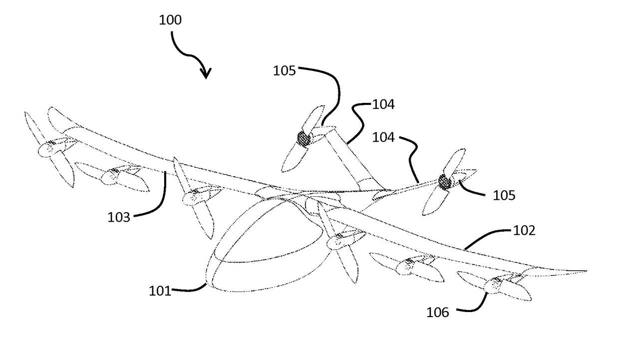
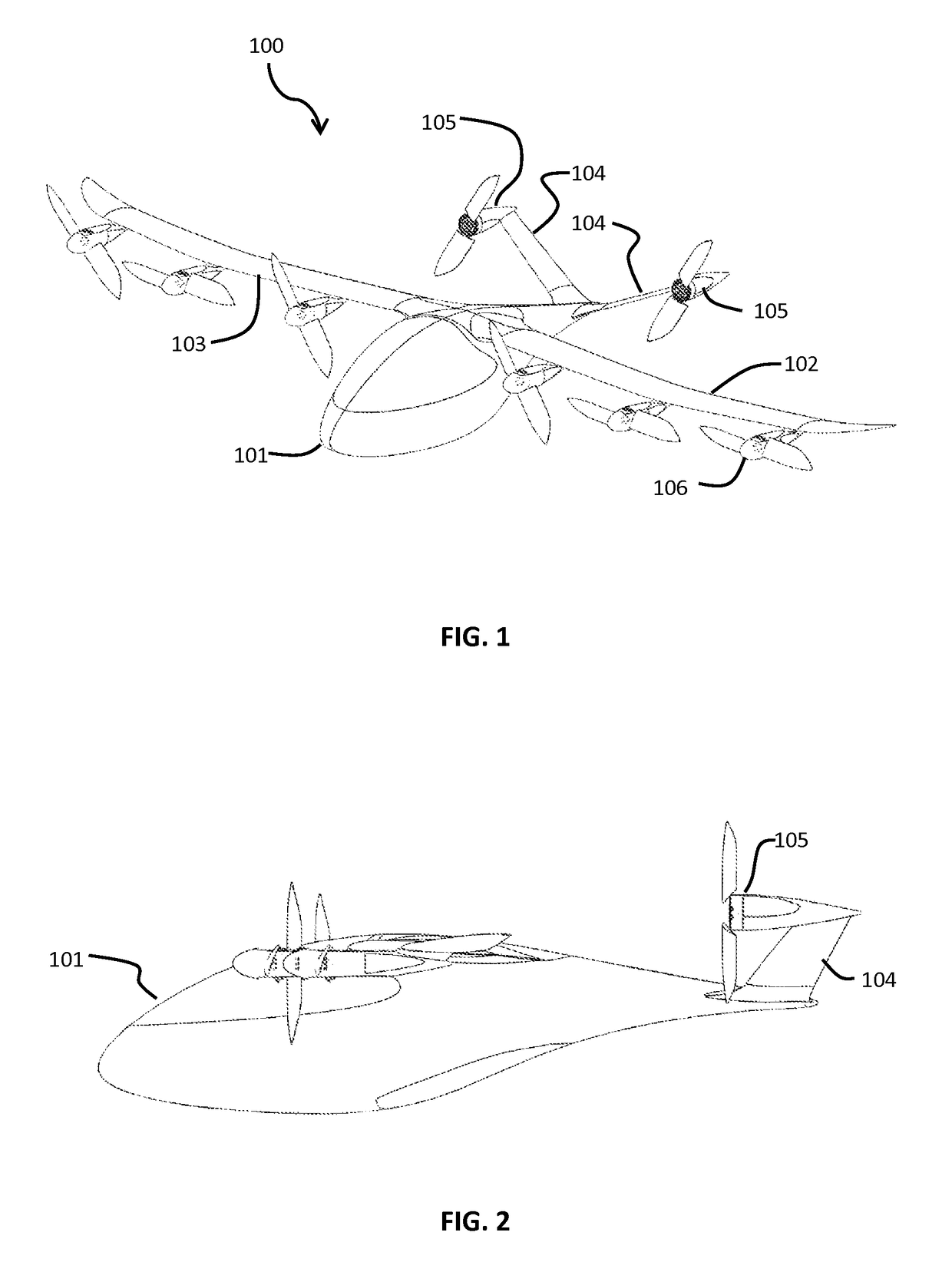
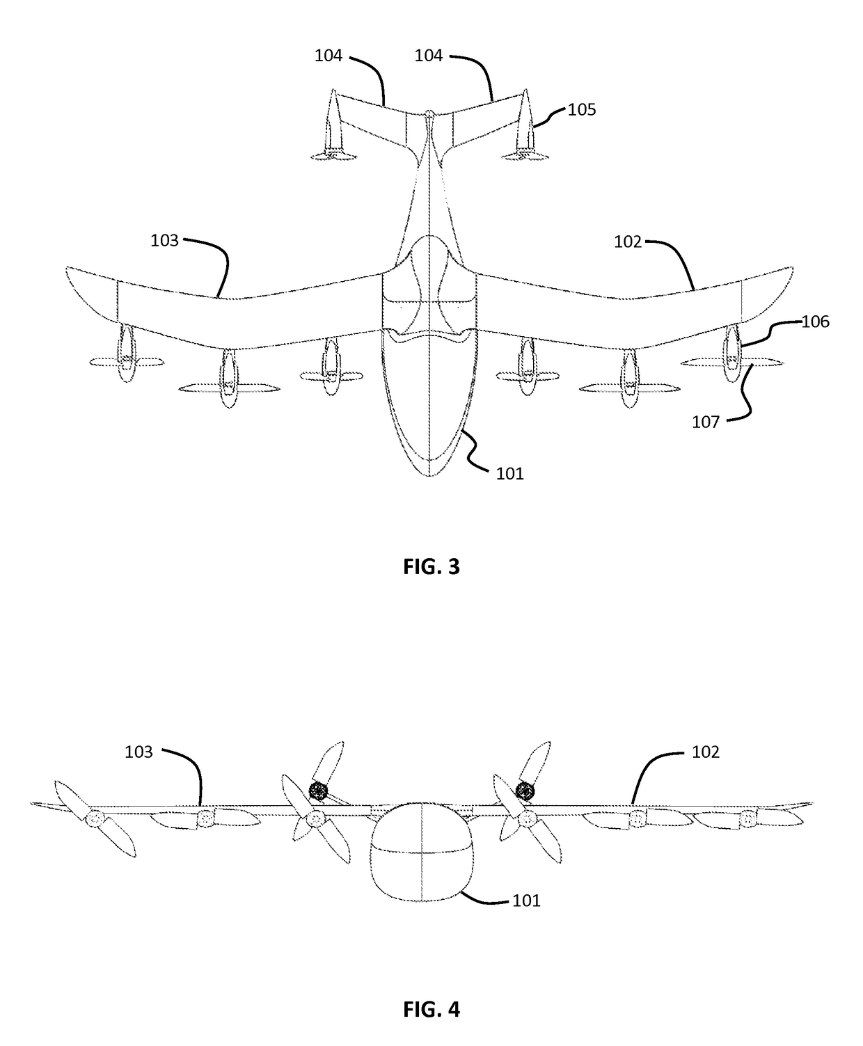
[0070]In the present invention, as seen in FIGS. 1-4, an aerial vehicle 100 is seen in first forward flight configuration, as would be seen just after having transitioned from a vertical take-off configuration. In another forward flight mode, the blades of the wing mounted rotors will stow and nest, as discussed below. The aircraft body 101 supports a left wing 102 and a right wing 103. Motor driven rotor units 106 include propellers 107 which may stow and nest into the nacelle body. The aircraft body 101 extends rearward is also attached to raised rear stabilizers 104. The rear stabilizers have rear motors 105 attached thereto. In some aspects, the rear motors may also have front hubs, or spinners, which are omitted from some Figures for illustrative purposes.

[0071]As seen in top view in FIG. 3, the wings 102, 103 are partially swept forward. Aerial vehicles according to embodiments of the present invention may include partially or wholly forward swept wings with spanwise distribut...

second embodiment

[0080]In the present invention, as seen in a vertical take-off configuration in FIGS. 29-32, an aerial vehicle 200 uses forward swept fixed wings 202, 203 with rotors of different types adapted for both vertical take-off and landing and for forward flight. The aircraft body 201 supports a left wing 202 and a right wing 203. Motor driven rotor assemblies 206, 207 on the wings include propellers which may stow and nest into the nacelle body. The aircraft body 201 extends rearward is also attached to raised rear stabilizers 204. The rear stabilizers have rear rotor assemblies 205, 208 attached thereto. The aerial vehicle 200 is seen with two passenger seats side by side, as well as landing gear under the body 201. Although two passenger seats are illustrated, other numbers of passengers may be accommodated in differing embodiments of the present invention.

[0081]As seen in top view in FIG. 32, the wings 202, 203 are swept forward. Aerial vehicles according to embodiments of the present ...

third embodiment

[0089]In the present invention, as seen in a vertical take-off configuration in FIGS. 45-48, an aerial vehicle 300 uses forward swept wings 302, 303 with rotors of different types adapted for both vertical take-off and landing and for forward flight. The aircraft body 301 supports a left wing 302 and a right wing 303. Motor driven rotor assemblies 306, 307 on the wings include propellers which may stow and nest into the nacelle body. The aircraft body 301 extends rearward and is also attached to raised rear stabilizers 304. The rear stabilizers have rear rotor assemblies 305, 308 attached thereto. The aerial vehicle 300 is adapted for two passenger seats side by side, as well as landing gear under the body 301.

[0090]The wing mounted rotor units 306, 307 are adapted to provide vertical thrust during take-off and landing modes. The inner rotor units 306 are adapted to deploy to a VTOL configuration using linkages as seen in FIG. 38. The blades of the inner wing rotor units 306 are ada...


PUM


Abstract

An aerial vehicle adapted for vertical takeoff and landing using a set of wing mounted thrust producing elements and a set of tail mounted rotors for takeoff and landing. An aerial vehicle which is adapted to vertical takeoff with the rotors in a rotated, take-off attitude then transitions to a horizontal flight path, with the rotors rotated to a typical horizontal configuration. The aerial vehicle uses different configurations of its wing mounted rotors and propellers to reduce drag in all flight modes.

Description

BACKGROUND[0001]Field of the Invention[0002]This invention relates to powered flight, and more specifically to a vertical take-off and landing aircraft with pivoting rotors and stowing rotor blades.[0003]Description of Related Art[0004]There are generally three types of vertical takeoff and landing (VTOL) configurations: wing type configurations having a fuselage with rotatable wings and engines or fixed wings with vectored thrust engines for vertical and horizontal translational flight; helicopter type configuration having a fuselage with a rotor mounted above which provides lift and thrust; and ducted type configurations having a fuselage with a ducted rotor system which provides translational flight as well as vertical takeoff and landing capabilities.[0005]The amount of thrust required to take-off in a vertical take-off scenario greatly exceeds the thrust needed to keep the same vehicle aloft during forward flight, when the wings are providing lift. The amount of thrust required...

Claims


Application Information

Patent Timeline
Patent Type & Authority Patents(United States)
IPC IPC(8): B64D27/24B64C39/06B64C11/28B64C29/00
CPCB64D27/24B64C11/28B64C29/0033B64C39/068Y02T50/62Y02T50/60
Inventor BEVIRT, JOEBENSTOLL, ALEX
Owner JOBY AERO INC
Why Eureka
Try Eureka