Mechanical embolization delivery apparatus and methods

a technology of mechanical embolism and delivery apparatus, which is applied in the field of neurovascular implants, can solve the problems of many mechanical delivery systems described herein, errors and frustration on the part of surgeons, and the reliability and robustness of the apparatus and method of operation, and achieve the effect of increasing the softness/flexibility of the distal end

Inactive Publication Date: 2017-07-11
THREE RIVERS MEDICAL INC
View PDF28 Cites 11 Cited by
  • Summary
  • Abstract
  • Description
  • Claims
  • Application Information

AI Technical Summary

Benefits of technology

[0021]As mentioned, the apparatuses described herein may be used with any appropriate implant, including, in particular, vascular coils such as embolization coils. The implant may be delivered to the targeted vessel location under fluoroscopy and standard endovascular technique using a commercially available micro catheter (MC), as will be described in greater detail below, the implant (e.g., coil) may then be mechanically detached from the detachable delivery wire using the handle (DH). Deployment of the apparatuses described herein may be particularly effectively and easily visualized to confirm delivery / detachment of the implant.
[0025]In general, the detachable delivery wire (DDW) is an elongate assembly that includes the pull wire within an inner lumen of the DDW. The enlarged distal end of the pull wire (or the region distal to a neck region) may be a ball, cylinder, or the like, and may be pre-loaded into the trap lumen of the hub assembly. The DDW also typically includes an outer pusher assembly having an inner lumen in which the pull wire resides. The pusher assembly may be formed of a hypotube or hypotubes, a coil or coils, a polymer tube or tubes, a braid or combinations of these, including serial and parallel arrangements of these. For example, the DDW may be formed of a distal coil region that may be jacketed (e.g., proximal to the distal end to increase the softness / flexibility of the distal end). Distal to the distal coil region may be a marker coil region (concentric coils or hypotube regions may be included as well, to adjust the overall stiffness / flexibility of the DDW). The proximal end of DDW may include a proximal hypotube. In some variations the proximal region may also include a strain relief hypotube, which may include a laterally elastic region, such as a spring region. The pull wire may be held (e.g., by a crimp, friction hold, internal detent, adhesive, etc.) within the pusher assembly so that the distal portion of the pull wire is in tension, pulling the hub assembly and attached implant against the distal end of the DDW. The strain relief hypotube may allow the tension on the distal end of the pull wire while still allowing the DDW to be flexible and bendable. The distal end of the DDW may be adapted to fit flush against the proximal end of the hub assembly. The DDW may be made of stainless steel and jacketed with a medical grade polymer. As mentioned, the DDW may include one or more marks, such as a safety marker, e.g., fluoro safety marker, or other visible marks, on the proximal shaft of the pusher assembly that provides a visual indication of when the implant (e.g., coil) is approaching but not exiting the distal end of the MC. In some variations the fluoro safety marker is on the proximal region of the shaft of the DDW and allows the user to see when an implant (e.g., coil) is approaching the distal end of a delivery catheter (e.g., microcatheter). The safety marker may, in some variations, be visualized with the naked eye or provide tactile feel. For example, a safety marker may include one or more colored region, such as one or more pieces of colored heat shrink material that is applied to the outside of the proximal stainless shaft.

Problems solved by technology

In particular, for non-mechanical systems (e.g., electrical, chemical or hydraulic release systems, the response time of actuating is delayed, which may lead to error and frustration on the part of the surgeon.
Many of the mechanical delivery systems described herein also suffer from problems associated with the reliability and robustness of the apparatus and method of operation.
Further, implants that are mechanically releasing implants from known systems may not be released with sufficient force, and may require direct visualization to confirm release.

Method used


Image

  • Mechanical embolization delivery apparatus and methods
  • Mechanical embolization delivery apparatus and methods
  • Mechanical embolization delivery apparatus and methods

Examples


Embodiment Construction

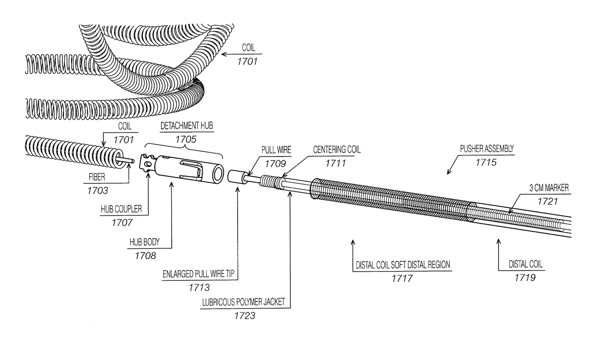
[0057]Described herein are mechanical delivery apparatuses and methods of using them to deliver neurovascular implants. In general, these mechanical delivery apparatuses may deliver quickly and may reliably release an implant (such as a vasoocclusive coil) from the delivery apparatus. This may ensure that the implant is released with minimal force so that the implant is not partially left in a vessel or neck of an aneurysm when filling the aneurysm. These apparatuses typically require a mechanical deformation (e.g., of a release or trap detent) to release and eject the implant.

[0058]For example, FIG. 4 shows one example of a system as described herein. In this example, the system includes an implant 401 (shown as a coil) affixed (permanently) to a hub assembly 403. The hub assembly includes an implant coupler (implant adapter) 405 to which the proximal end of the coil is affixed. The implant coupler is also permanently connected to the deformable mechanical release (trap) 407. The d...


PUM


Abstract

Mechanical delivery system for neurovascular embolization apparatus and method of use. A mechanical system for delivery of implants, such as coils for endovascular embolization of intracranial aneurysms and other neurovascular abnormalities such as arteriovenous malformations and ateriovenous fistulae, may include a detachment system for the release of a coil that deforms a detent to release (or eject) the implant.

Description

CROSS REFERENCE TO RELATED APPLICATIONS[0001]This patent application claims priority to U.S. Provisional Patent Application No. 62 / 241,316, titled “MECHANICAL EMBOLIZATION DELIVERY APPARATUS AND METHODS” filed on Oct. 14, 2015 and U.S. Provisional Patent Application No. 62 / 348,710, titled“MECHANICAL EMBOLIZATION DELIVERY APPARATUS AND METHODS” filed on Jun. 10, 2016, each of which is herein incorporated by reference in its entirety.INCORPORATION BY REFERENCE[0002]All publications and patent applications mentioned in this specification are herein incorporated by reference in their entirety to the same extent as if each individual publication or patent application was specifically and individually indicated to be incorporated by reference.FIELD[0003]Mechanical delivery apparatuses and methods for neurovascular implants.BACKGROUND[0004]Described herein are medical devices for placing an implant such as an embolic device at a predetermined site within a vessel or lumen of a human (or an...

Claims


Application Information

Patent Timeline
Patent Type & Authority Patents(United States)
IPC IPC(8): A61M29/00A61B90/00A61B17/12
CPCA61B17/12145A61B17/12113A61B90/39A61B2017/12054A61B2090/3966A61B2017/1205A61B2090/0811A61B17/1214
Inventor DIAS, MARK ANDREWAFAN, RICARDO MANABATGARABEDIAN, ROBERT
Owner THREE RIVERS MEDICAL INC
Why Eureka
Try Eureka