Systems and methods for regulating the resonant frequency of a disc pump cavity

a disc pump and cavity technology, applied in the field of disc pumps, can solve the problems that the acoustic resonance of high amplitude disc pumps has not been employed, and achieve the effect of reducing the dampening of displacement oscillations

Active Publication Date: 2017-07-18
3M INNOVATIVE PROPERTIES CO
View PDF150 Cites 0 Cited by
  • Summary
  • Abstract
  • Description
  • Claims
  • Application Information

AI Technical Summary

Benefits of technology

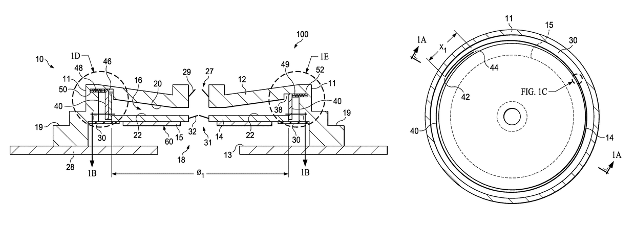
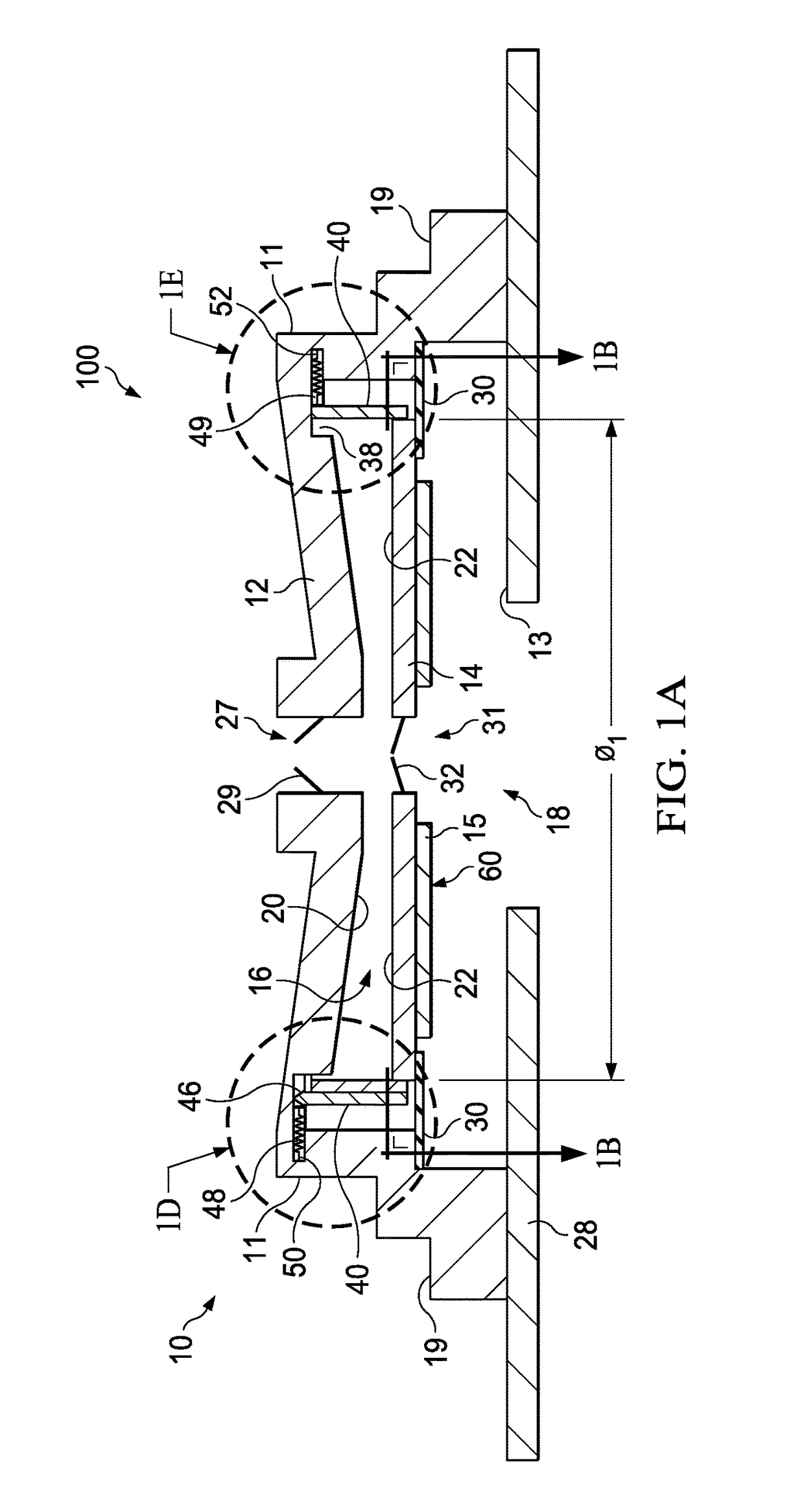
[0011]According to an illustrative embodiment, a disc pump system includes a pump body having a substantially cylindrical shape defining a cavity for containing a fluid. The cavity is formed by an internal sidewall closed at both ends by a first end wall and a driven end wall having a central portion and a peripheral portion extending radially outwardly from the central portion. The disc pump system includes an actuator operatively associated with the central portion of the driven end wall to cause an oscillatory motion of the driven end wall at a frequency (f), thereby generating displacement oscillations of the driven end wall in a direction substantially perpendicular thereto. The frequency (f) being about equal to a fundamental bending mode of the actuator. The disc pump system also includes a drive circuit having an output electrically coupled to the actuator for providing the drive signal to the actuator at the at the frequency (f), as well as an isolator operatively associated with the peripheral portion of the driven end wall to reduce dampening of the displacement oscillations. A first aperture is disposed at any location in either one of the end walls other than at the annular node and extending through the pump body. Similarly, a second aperture is disposed at any location in the pump body other than the location of the first aperture and extending through the pump body. A valve is disposed in at least one of the first aperture and the second aperture, and the displacement oscillations generate corresponding pressure oscillations of the fluid within the cavity of the pump body causing fluid flow through the first aperture and second aperture.

Problems solved by technology

However, high amplitude acoustic resonance has not been employed within disc-shaped cavities in which radial pressure oscillations are excited until recently.

Method used


Image

  • Systems and methods for regulating the resonant frequency of a disc pump cavity
  • Systems and methods for regulating the resonant frequency of a disc pump cavity
  • Systems and methods for regulating the resonant frequency of a disc pump cavity

Examples


Embodiment Construction

[0035]In the following detailed description of illustrative embodiments, reference is made to the accompanying drawings that form a part hereof. By way of illustration, the accompanying drawings show specific preferred embodiments in which the invention may be practiced. These embodiments are described in sufficient detail to enable those skilled in the art to practice the invention, and it is understood that other embodiments may be utilized and that logical structural, mechanical, electrical, and chemical changes may be made without departing from the spirit or scope of the invention. To avoid detail not necessary to enable those skilled in the art to practice the embodiments described herein, the description may omit certain information known to those skilled in the art. The following detailed description is, therefore, not to be taken in a limiting sense, and the scope of the illustrative embodiments are defined only by the appended claims.

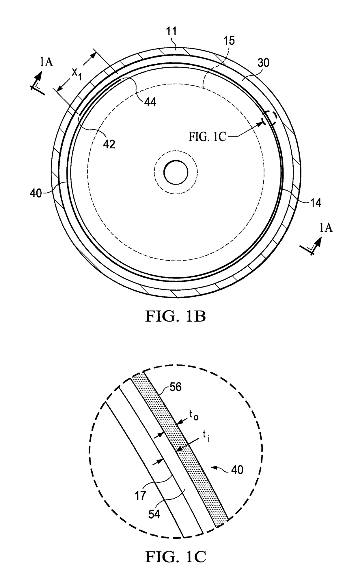
[0036]FIGS. 1A-1E show an illustrative ...


PUM


Abstract

A disc pump system includes a pump body having a substantially cylindrical shape defining a cavity for containing a fluid. The cavity having a resonant cavity frequency is formed by an internal sidewall and substantially closed at both ends by a first end wall and a driven end wall. The disc pump system includes an actuator that is driven a frequency (f) that corresponds to the fundamental resonant frequency of the actuator. The internal sidewall is configured to expand and contract in response to changes in temperature, thereby causing the actuator and cavity to have approximately the same resonant frequencies over a range of operating temperatures.

Description

[0001]The present invention claims the benefit, under 35 USC §119(e), of the filing of U.S. Provisional Patent Application Ser. No. 61 / 668,100, entitled “Systems and Methods for Regulating the Resonant Frequency of a Disc Pump,” filed Jul. 5, 2012, by Locke et al., which is incorporated herein by reference for all purposes.BACKGROUND OF THE INVENTION[0002]1. Field of the Invention[0003]The illustrative embodiments of the invention relate generally to a disc pump for pumping fluid and, more specifically, to a disc pump in which the pumping cavity is formed by an internal sidewall and opposing end walls. The illustrative embodiments of the invention relate more specifically to a disc pump with a cavity that has a variable resonant frequency.[0004]2. Description of Related Art[0005]The generation of high amplitude pressure oscillations in closed cavities has received significant attention in the fields of thermo-acoustics and disc pump type compressors. Recent developments in non-linea...

Claims


Application Information

Patent Timeline
Patent Type & Authority Patents(United States)
IPC IPC(8): F04B17/03F04B43/04F04F7/00F04B17/00F04B19/00
CPCF04B17/00F04B19/006F04B43/04F04B43/046F04F7/00
Inventor LOCKE, CHRISTOPHER BRIANTOUT, AIDAN MARCUS
Owner 3M INNOVATIVE PROPERTIES CO
Why Eureka
Try Eureka