Method of operating a leaky integrator, leaky integrator and apparatus comprising a leaky integrator

a leaky integrator and integrator technology, applied in the field of leaky integrators and integrators, can solve problems such as not giving complete satisfaction, and achieve the effect of reducing enhancing the dampening of input signals

Active Publication Date: 2020-09-17
STMICROELECTRONICS (RES & DEV) LTD
View PDF0 Cites 0 Cited by
  • Summary
  • Abstract
  • Description
  • Claims
  • Application Information

AI Technical Summary

Benefits of technology

[0017]The greater the frequency of the periodic oscillations, the lower Δ1 and therefore the greater the dampening of the input signal may be. The lower the frequency of the periodic oscillations, the greater Δ1 and therefore the lower the dampening of the input signal may be.

Problems solved by technology

With existing functions a problem may arise when the scene comprises lights flashing periodically (e.g., indicators of a car) with a frequency in the order of 1 Hz or lights entering and leaving periodically (e.g., tunnel with overhead lighting) with a frequency in the order of 1 Hz.
However, conventional leaky integrators only partially attenuate visible artefacts in the final images rendered on the display and therefore do not give entire satisfaction.

Method used


Image

  • Method of operating a leaky integrator, leaky integrator and apparatus comprising a leaky integrator
  • Method of operating a leaky integrator, leaky integrator and apparatus comprising a leaky integrator
  • Method of operating a leaky integrator, leaky integrator and apparatus comprising a leaky integrator

Examples


Embodiment Construction

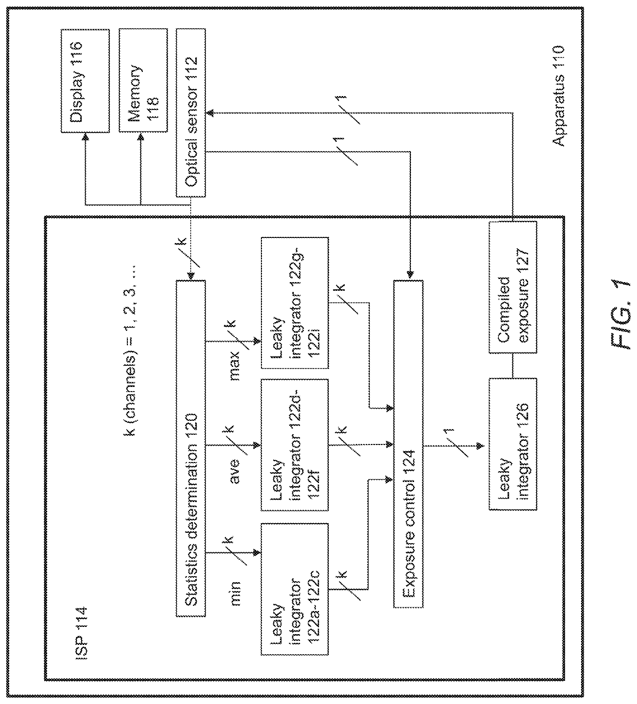
[0092]FIG. 1 shows a schematic representation of an apparatus 110. The apparatus 110 may comprise a mobile phone, a tablet computer, a desktop computer, a laptop computer, a video game console, a video door, a smart watch, a vehicle or the like.

[0093]The apparatus 110 may comprise an optical sensor 112 (e.g., digital camera) configured to capture images of a scene. Each image may comprise one or more channels, such as a red channel, a green channel and a blue channel. Each image may be characterized by one or more characteristics, such as a brightness, a dynamic range, a contrast, a resolution or other characteristics. Each characteristic may be adjusted by one or more parameters of the optical sensor 112, such as an exposure parameter, a shutter speed parameter, a channel gain parameter, a channel curve parameter or other parameters.

[0094]The apparatus 110 may comprise an image signal processor (ISP) 114 configured to process the images of the scene captured by the optical sensor 1...


PUM


Abstract

The present disclosure relates to receiving an input signal; generating an output signal by integrating a leaked signal over an integration time, wherein the leaked signal is obtained based on a dampening signal, a leak factor and the input signal; and providing the output signal.

Description

BACKGROUNDTechnical Field[0001]The present disclosure relates to a method of operating a leaky integrator, a leaky integrator and an apparatus comprising a leaky integrator.Description of the Related Art[0002]Some apparatus (e.g., mobile phones, tablet computers, laptop computers, desktop computers, video game consoles, smart card readers, video cameras, televisions, vehicles, etc.) may be equipped with one or more optical sensors to capture images of a scene. These apparatus may be equipped with one or more functions (e.g., white balance control, exposure control, tone mapping control, etc.) to adjust characteristics of the final images (e.g., brightness, dynamic range, contrast, etc.) rendered on a display.[0003]With existing functions a problem may arise when the scene comprises lights flashing periodically (e.g., indicators of a car) with a frequency in the order of 1 Hz or lights entering and leaving periodically (e.g., tunnel with overhead lighting) with a frequency in the ord...

Claims


Application Information

Patent Timeline
Patent Type & Authority Applications(United States)
IPC IPC(8): H04N5/359
CPCH04N5/359H03K5/22H04N9/73H04N9/643H04N23/741H03H17/0294H04N23/71H04N23/88G06T5/009H04N23/745H04N23/75
Inventor STEWART, BRIAN DOUGLAS
Owner STMICROELECTRONICS (RES & DEV) LTD
Why Eureka
Try Eureka