Pixel with Switchable High Gain and High Capacity Modes

a high-capacity, switchable technology, applied in the field of high-capacity pixels with switchable high-capacity modes, can solve the problems of reducing the dynamic range of the pixel, doubling the readout bandwidth requirements, and affecting the overall system power, and achieves high signal-to-noise ratio, high gain, and inherent noise signals.

Active Publication Date: 2016-07-07
FORZA SILICON
View PDF4 Cites 12 Cited by
  • Summary
  • Abstract
  • Description
  • Claims
  • Application Information

AI Technical Summary

Benefits of technology

[0009]An IR ROIC has a fixed well capacity of electrons that can be integrated per cycle, and also has an inherent noise signal. In a low light imaging context, it is advantageous to use a high gain amplifier, wherein a high signal to noise ratio insures that the low input signal is not swamped by noise. The sensitivity that is attained using a high gain amplifier is further enhanced if CDS operations are used as well. However, the use of a high gain amplifier means that the dynamic range of the pixel is reduced, and bright portions of a scene will saturate the well capacity of the sensor. In order to maximize pixel well capacity, the amplifier gain must be kept low, which is not ideal for dimly lit scenes where noise is an issue. The choice between maximizing sensitivity and maximizing capacity is not available in prior art IR sensor pixel designs, which are generally constrained to a single sensitivity and well capacity setting and are not optimized for both low and high light.
[0010]Advantageously, the present invention provides the art with a solution to this quandary. Disclosed herein is a novel pixel readout architecture which allows the pixel to be run in either a high sensitivity mode or a high capacity mode, as described below.

Problems solved by technology

There can be significant overhead to implementing the CDS function downstream from the pixel, in that two successive reads are required, thus doubling the readout bandwidth requirements and impacting overall system power.
However, the use of a high gain amplifier means that the dynamic range of the pixel is reduced, and bright portions of a scene will saturate the well capacity of the sensor.
In order to maximize pixel well capacity, the amplifier gain must be kept low, which is not ideal for dimly lit scenes where noise is an issue.
The choice between maximizing sensitivity and maximizing capacity is not available in prior art IR sensor pixel designs, which are generally constrained to a single sensitivity and well capacity setting and are not optimized for both low and high light.

Method used


Image

  • Pixel with Switchable High Gain and High Capacity Modes
  • Pixel with Switchable High Gain and High Capacity Modes

Examples


Embodiment Construction

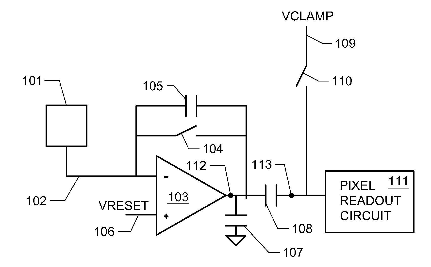
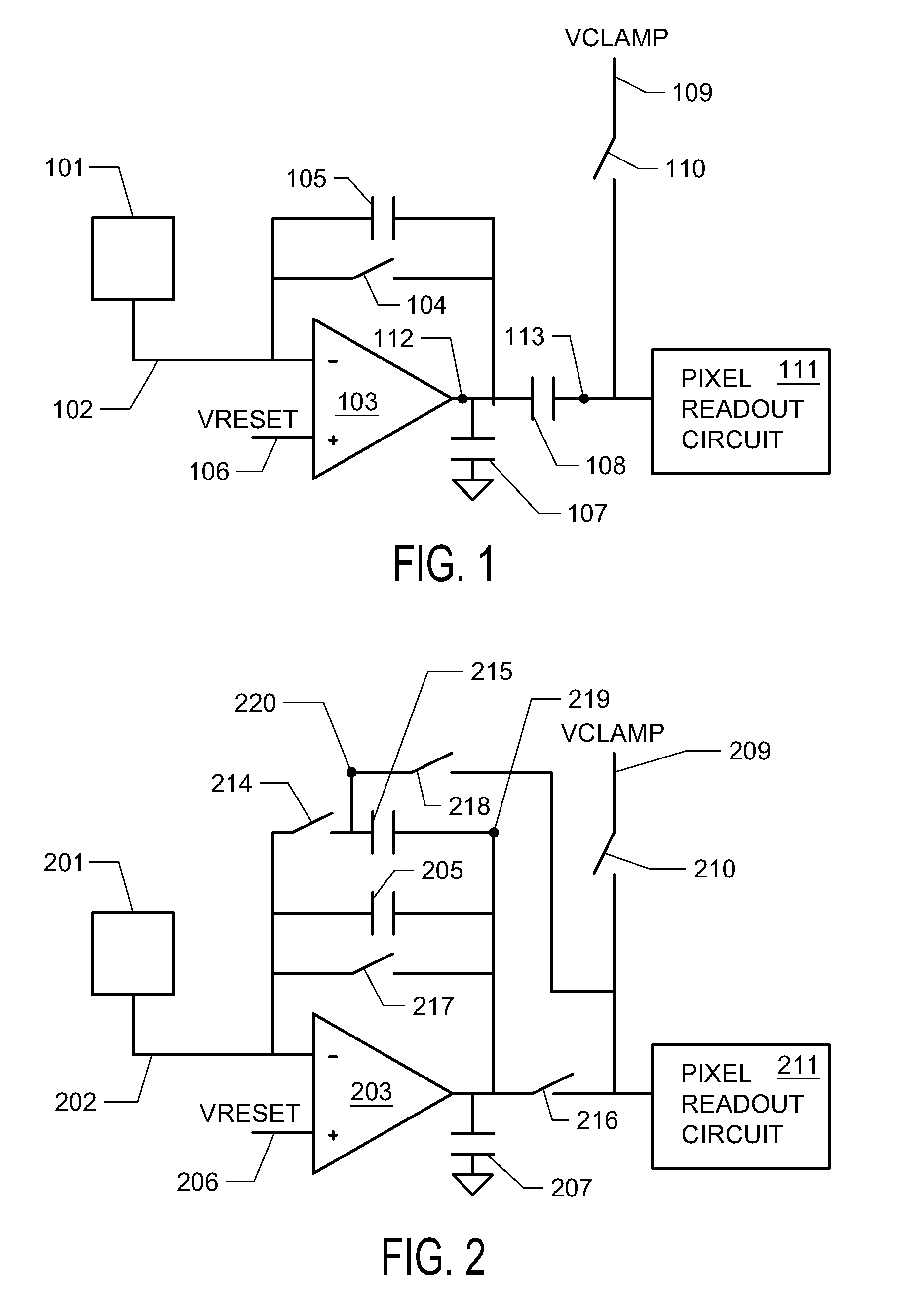
[0013]The invention encompasses the use a dual-use capacitor that can be deployed in one of two functions. In one mode, the dual-use capacitor is utilized to store the pixel reset signal and allows the implementation of in-pixel CDS. In this mode, the amplifier feedback factor is low and amplifier gain is high. Thus, in this mode of operation the pixel is optimized for high sensitivity imaging, with high signal to noise ratio and CDS functionality enabled to further reduce the impact of noise on the signal measurement.

[0014]In the alternative mode, the dual-use capacitor is deployed to increase the capacitance of the CTIA feedback loop, resulting in lower amplifier gain, meaning that a larger range of input signal can fit within the pixel's capacity to accumulate charge. In this mode, the pixel is optimized for higher dynamic range.

[0015]The invention provides an efficient use of limited space to extend the capabilities of the pixel. As the demand for higher resolution arrays and sm...


PUM


Abstract

Provided herein is a novel pixel circuit for image sensors such as IR ROIC image sensors. The design provides a switchable pixel with two modes. In the first mode, the pixel performs in-pixel correlated double sampling to remove reset noise. In the second mode, the pixel is configured in a high-capacity mode to avoid saturation. The pixel may be dynamically switched between modes, for example in response to lighting conditions in the scene to be imaged.

Description

CROSS-REFERENCE TO RELATED APPLICATIONS[0001]This application claims the benefit of priority to U.S. Provisional Application Ser. No. 62 / 100,540 entitled “Pixel with Switchable High Gain and High Capacity Modes,” filed Jan. 7, 2015, the contents of which are hereby incorporated by reference.REFERENCE TO SEQUENCE LISTING, A TABLE, OR A COMPUTER PROGRAM LISTING COMPACT DISK APPENDIX[0002]Not Applicable.STATEMENT REGARDING FEDERALLY SPONSORED RESEARCH OR DEVELOPMENT[0003]Not Applicable.BACKGROUND AND SUMMARY OF THE INVENTION[0004]Infrared image sensors are widely used in a variety of applications. Many such sensors rely on pixels having a charge transimpedance amplifier (CTIA) pixel design.[0005]Reset noise is a dominant noise source in CTIA-based pixels. One strategy for reducing such noise is the use of correlated double sampling (CDS), wherein the level of accumulated charge in the reset pixel is measured and this measurement is subtracted from the signal charge to remove the noise...

Claims


Application Information

Patent Timeline
Patent Type & Authority Applications(United States)
IPC IPC(8): H04N5/33H04N5/232H04N5/378
CPCH04N5/33H04N5/23245H04N5/378H04N25/59H04N25/616H04N25/75
Inventor BAGWELL, SAMBERGEY, JONATHANESTRADA, DAVID
Owner FORZA SILICON
Why Eureka
Try Eureka