Hydraulic Dampener Systems

a technology of hydraulic dampener and dampener, which is applied in the direction of vibration dampers, shock absorbers, liquid based dampers, etc., can solve the problems of increasing dampening, and achieve the effects of increasing dampening, improving hydraulic dampener systems, and reducing dampening

Active Publication Date: 2014-09-18
WALACH MFG CO
View PDF6 Cites 1 Cited by
  • Summary
  • Abstract
  • Description
  • Claims
  • Application Information

AI Technical Summary

Benefits of technology

[0006]The present disclosure provides improved hydraulic dampener systems. The systems disclosed here are designed for a sealed self-contained hydraulic dampener in which the dampening may be controlled by rotating the cylindrical housing body of the system. For example, rotating the housing body in one direction may increase the dampening and rotating the housing in the opposite direction may decrease the dampening. The system allows the rate of dampening to be controlled when the system is at rest or in motion. In addition, the dampening setting does not change unless it is intentionally adjusted. Further, the dampener system may be mounted and used in a horizontal or vertical orientation.

Problems solved by technology

As the piston is screwed along the thread of the shaft, hydraulic fluid flow is decreased as a function of the size of the passage decreasing, thus increasing the dampening.

Method used


Image

  • Hydraulic Dampener Systems
  • Hydraulic Dampener Systems
  • Hydraulic Dampener Systems

Examples


Embodiment Construction

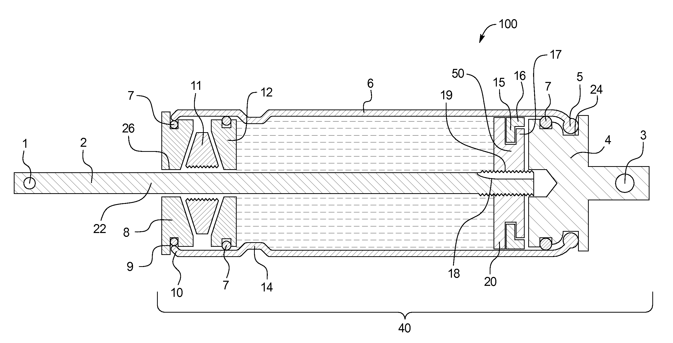
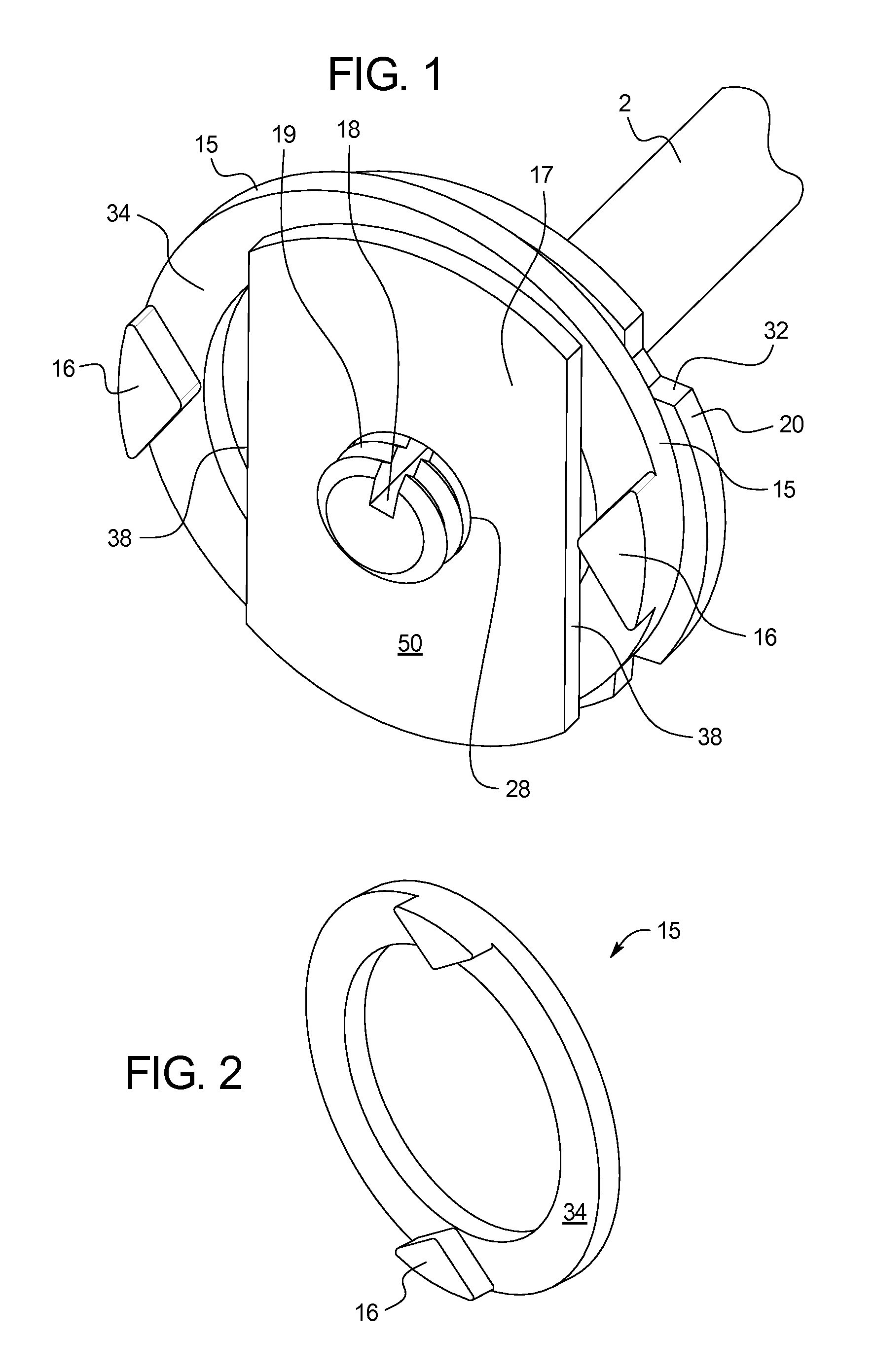
[0037]The present disclosure provides hydraulic dampener systems 100 including a piston 50, a washer 15, and a shaft 2, as shown in FIG. 1. The piston 50 includes a threaded central opening 28 that is configured to engage a threaded surface of the shaft 2. In an example, the treaded surface of the shaft 2 and the threaded central opening 28 of the piston 50 define a class 5 interference fit. The piston 50 may be made of any suitable material including, but not limited to, metal, plastic, resin, among others. For example, the piston 50 may be made of fiberglass reinforced nylon, such as, Zytel®.

[0038]The piston 50 includes a piston front disk 17 and a piston back disk 20. As shown in FIG. 1, a measurement taken across the face of the piston front disk 17 and extending through the threaded central opening 28 is smaller than a diameter of the piston back disk 20. In an example, the reduced size is achieved because the piston front disk 17 includes two flat sections 38 along its perimet...


PUM


Abstract

The present disclosure provides hydraulic dampening systems wherein the dampening effect may be controlled by rotating a body of the dampener, after the dampening system has been installed and in use. The system includes a piston including a front disk and back disk, wherein the front disk has a reduced diameter with respect to the back disk. A washer is positioned between the two piston disks, wherein the diameter of the washer is greater than the piston back disk, wherein the washer includes at least two protruding tabs. The washer is frictionally engaged with the body of the dampener. As the body is rotated, the washer is rotated such that the washer tabs engage at least a portion of the piston front disk to rotate the piston along a threaded surface of a shaft of the system.

Description

CROSS-REFERENCE TO RELATED APPLICATIONS[0001]This application incorporates by reference and claims priority to U.S. Provisional Application 61 / 780,875 filed on Mar. 13, 2013.BACKGROUND OF THE INVENTION[0002]The present subject matter relates generally to a hydraulic dampener system, wherein a user controls the degree of dampening by rotating a cylindrical housing of the system.[0003]Conventional hydraulic dampeners incorporate an adjustment means to control the flow of hydraulic fluid, which in turn controls the degree of dampening. Conventional adjustment techniques typically include the application of a separate tool to adjust the dampening effect. Further, conventional designs only allow a user to adjust the dampening before the dampener is mounted into place. Once the dampener is installed, a user cannot adjust the dampening without removing the dampener from the mounting. After which, a user must remount and reinstall the dampener.[0004]In other dampeners, the degree of dampeni...

Claims


Application Information

Patent Timeline
Patent Type & Authority Applications(United States)
IPC IPC(8): F16F9/44F16F9/19
CPCF16F9/19F16F9/44F16F9/3405F16F9/3415
Inventor WALACH, DAVID P.
Owner WALACH MFG CO
Why Eureka
Try Eureka