Structured illumination apparatus, structured illumination microscopy apparatus, and profile measuring apparatus

a microscopy and structure technology, applied in the direction of fluorescence/phosphorescence, instruments, optical elements, etc., can solve the problems of reducing the time required to completely obtain the required images, the complexity of the optical system of a super-resolution microscope, and the adjustment of the optical system and the cos

Active Publication Date: 2017-07-18
NIKON CORP
View PDF23 Cites 1 Cited by
  • Summary
  • Abstract
  • Description
  • Claims
  • Application Information

AI Technical Summary

Benefits of technology

[0013]Accordingly, the present application has a proposition to provide a structured illumination apparatus having a configuration suitable for increasing a speed of obtaining images, an efficient structured illumination microscopy apparatus, and an efficient profile measuring apparatus.

Problems solved by technology

However, when an optical element is moved in steps, a certain period of time is required for stopping the moving optical element at an appropriate position, so that it is difficult, in the method of Patent Document 2, to reduce a period of time required to completely obtain the required images.
Further, in a method of using four acousto-optical elements as the method of Non-Patent Document 2, an optical system of a super-resolution microscope becomes complicated, and due to the complication of the system, there is a disadvantage in the aspect of the adjustment of the optical system and the cost.

Method used


Image

  • Structured illumination apparatus, structured illumination microscopy apparatus, and profile measuring apparatus
  • Structured illumination apparatus, structured illumination microscopy apparatus, and profile measuring apparatus
  • Structured illumination apparatus, structured illumination microscopy apparatus, and profile measuring apparatus

Examples


first embodiment

Supplement to First Embodiment

[0139]Note that the CPU of the present embodiment performs the frequency adjustment every time the series of three pieces of image data (the pieces of image data Ia1, Ia2, and Ia3, the pieces of image data Ib1, Ib2, and Ib3, or the pieces of image data Ic1, Ic2, and Ic3) are obtained, but, it is also possible to perform the frequency adjustment for a predetermined period of time. Alternatively, it is also possible to measure a period of time of continuous energization with respect to the ultrasonic wave light modulator 3, and to perform the frequency adjustment every time the period of time of continuous energization reaches a predetermined period of time. However, in any of the above cases, it is desirable that the frequency is not changed in the middle of the obtainment of the series of three pieces of image data (the pieces of image data Ia1, Ia2, and Ia3, the pieces of image data Ib1, Ib2, and Ib3, or the pieces of image data Ic1, Ic2, and Ic3).

[014...

second embodiment

[0145]Hereinafter, a second embodiment of the present invention will be described by using the drawings. The present embodiment is a modified example of the first embodiment. Here, only a point of difference between the present embodiment and the first embodiment will be described.

[0146]The point of difference is that a heat releasing function is added to the ultrasonic wave light modulator 3. Instead of that, a frequency of the frequency adjustment (or the amplitude adjustment or the charge storing time adjustment) in the present embodiment is reduced, compared to that in the first embodiment. Alternatively, the frequency adjustment (or the amplitude adjustment or the charge storing time adjustment) is omitted.

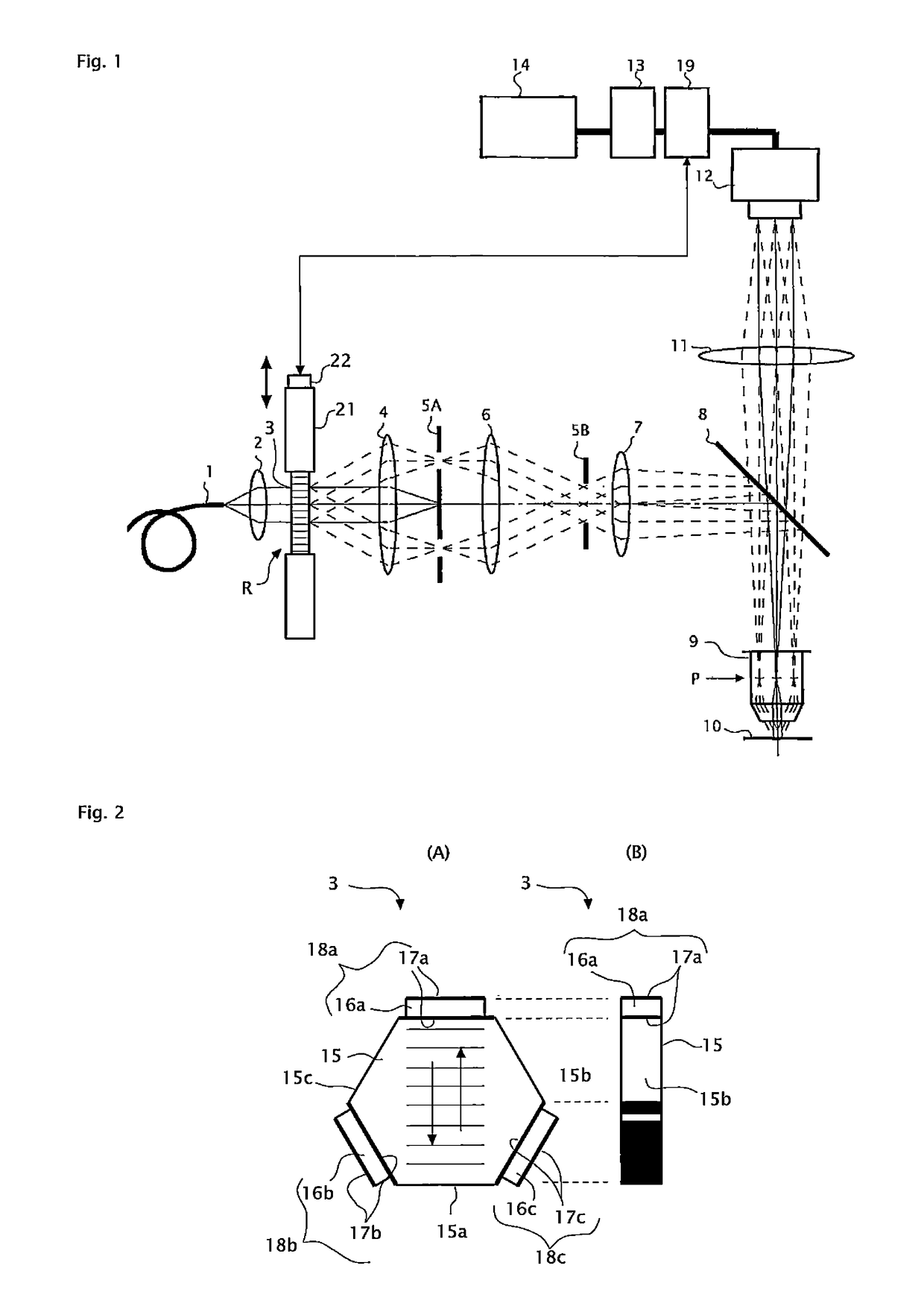
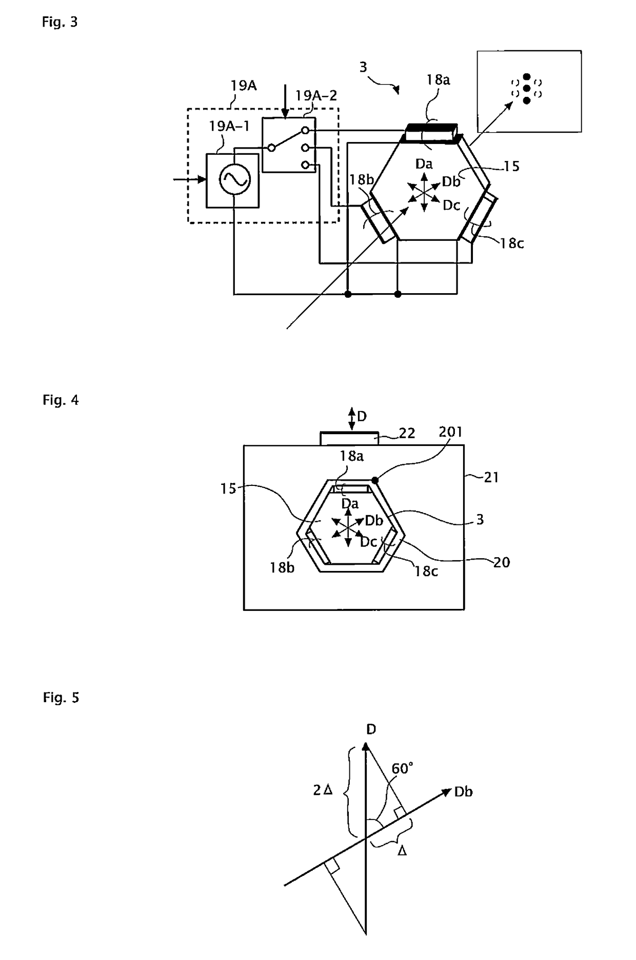
[0147]FIG. 9 is a diagram in which a periphery of the ultrasonic wave light modulator 3 in the second embodiment is seen from an optical axis direction, and FIG. 10 is a sectional diagram obtained by cutting the ultrasonic wave light modulator 3 along a plane X-X′ (plane bein...

third embodiment

[0162]Hereinafter, a third embodiment of the present invention will be described by using the drawings. The present embodiment is a modified example of the first embodiment. Here, only a point of difference between the present embodiment and the first embodiment will be described.

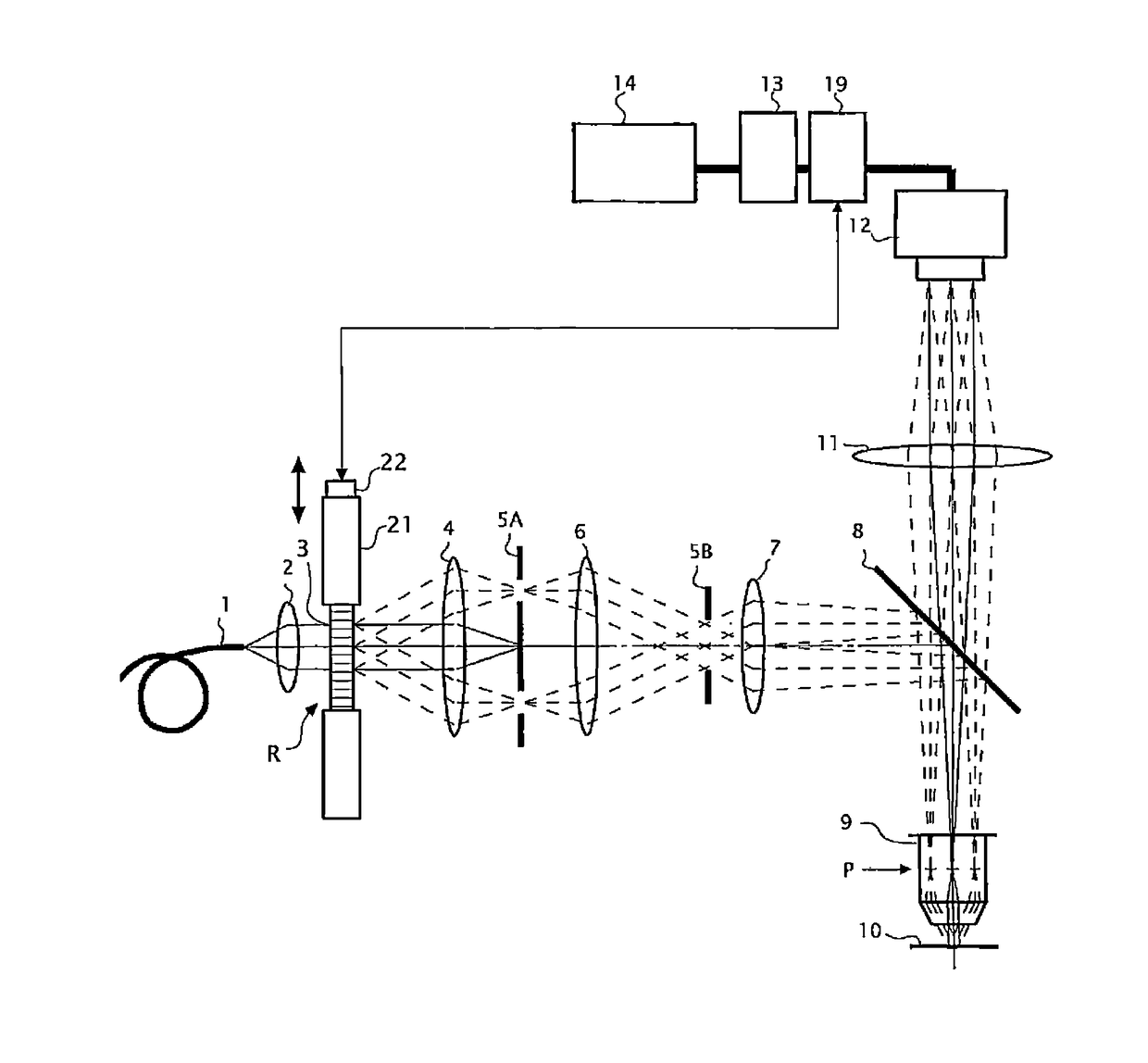
[0163]FIG. 11 is a configuration diagram of a structured illuminating microscopy system of the present embodiment. As illustrated in FIG. 11, in the present embodiment, the piezoelectric actuator 22 is omitted, and the function of shifting the phase of the structured illumination is realized by the controlling device 19.

[0164]The controlling device 19 controls the ultrasonic standing wave generated in the ultrasonic wave propagation path R of the ultrasonic wave light modulator 3, to thereby change the amount of phase shift of the structured illumination, in steps, by 2π / 3 (details will be described later). Further, the controlling device 19 drives the imaging device 12 when the phases of structured illumin...


PUM

PropertyMeasurementUnit
resolving powersaaaaaaaaaa
angleaaaaaaaaaa
angleaaaaaaaaaa

Abstract

A structured illumination apparatus includes a light modulator being disposed in an exit flux of light from a light source and in which a sonic wave propagation path is arranged in a direction traversing the exit flux of light; a driving unit generating a sonic standing wave in the sonic wave propagation path by giving a driving signal for vibrating a medium of the sonic wave propagation path to the light modulator; and an illuminating optical system making mutually different diffracted components of the exit flux of light passed through the sonic wave propagation path to be interfered with each other, and forming interference fringes of the diffracted components on an observational object.

Description

CROSS REFERENCE TO THE RELATED APPLICATIONS[0001]This application is a continuation application of International Application PCT / JP2011 / 005682, filed Oct. 11, 2011, designating the U.S., and claims the benefit of priority from Japanese Patent Application No. 2010-231458 and Japanese Patent Application No. 2011-087068, filed on Oct. 14, 2010 and Apr. 11, 2011, respectively, the entire contents of which are incorporated herein by reference.BACKGROUND[0002]1. Field[0003]The present application relates to a structured illumination apparatus, a structured illumination microscopy apparatus, and a pattern projection type profile measuring apparatus capable of realizing a super resolution in an in-plane direction.[0004]2. Description of the Related Art[0005]A super-resolution microscope is one that modulates an illumination light flux that illuminates a sample plane and demodulates an image-forming light flux which is incident on a position that is substantially conjugated with the sample p...

Claims


Application Information

Patent Timeline
Patent Type & Authority Patents(United States)
IPC IPC(8): G01B9/02G02B21/16G02B21/06G01B11/24G01N21/64
CPCG02B21/16G02B21/06G01B11/24G01N21/6458G02B2207/113G02B27/425G02B27/58
Inventor NOMURA, TATSUSHI
Owner NIKON CORP
Why Eureka
Try Eureka