Implant delivery devices, systems, and methods

a technology of implant delivery and delivery device, applied in the field of implant delivery device, system and method, can solve the problem of limited working space for delivery of implants

Active Publication Date: 2017-08-01
OCULEVE
View PDF256 Cites 29 Cited by
  • Summary
  • Abstract
  • Description
  • Claims
  • Application Information

AI Technical Summary

Benefits of technology

[0006]In some variations, the devices described here may further comprise a rocker, wherein the rocker is rotatably connected to the handle, wherein the device is configured such that rotation of the rocker in a first direction to a first position moves the piercing member to the piercing configuration, and wherein rotation of the rocker in a second direction opposite the first direction to a second position moves the piercing member to the retracted configuration. In some of these variations, the rocker may be biased toward the second position. In variations where the device comprises a control slider, the control slider may be configured to rotate the rocker in the first direction. In some of these variations, the control slider may comprise a button, wherein depression of the button rotates the rocker in the first direction. In some of these variations, the control slider may be slidable along the handle between a retracted position and an advanced position, and the handle may configured to allow depression of the button when the control slider is in the retracted position and to prevent depression of the button when the control slider is in the advanced position.
[0011]In some variations, the tongue may be moveable between a retracted position in which a distal end of the tongue is positioned in the channel and an advanced position in which a distal end of the tongue is positioned distally of the outlet of the channel. In some of these variations, the tongue may comprise a handle, wherein the handle is sized to be prevented from entering the inlet, and wherein the handle of the tongue contacts the inlet when the tongue is in the advanced position. In some of these variations, the distal end of the tongue is positioned distal to a distal end of the blade when the tongue is in the advanced position. Additionally or alternatively, the plunger may comprise a handle, and the plunger and tongue may be positioned such that the handle of the tongue is prevented from being withdrawn proximally of the handle of the plunger.

Problems solved by technology

The presence of these anatomical structures within the orbit, which in some instances may be easily damaged, can provide a limited working space for delivery of implants.

Method used


Image

  • Implant delivery devices, systems, and methods
  • Implant delivery devices, systems, and methods
  • Implant delivery devices, systems, and methods

Examples


Embodiment Construction

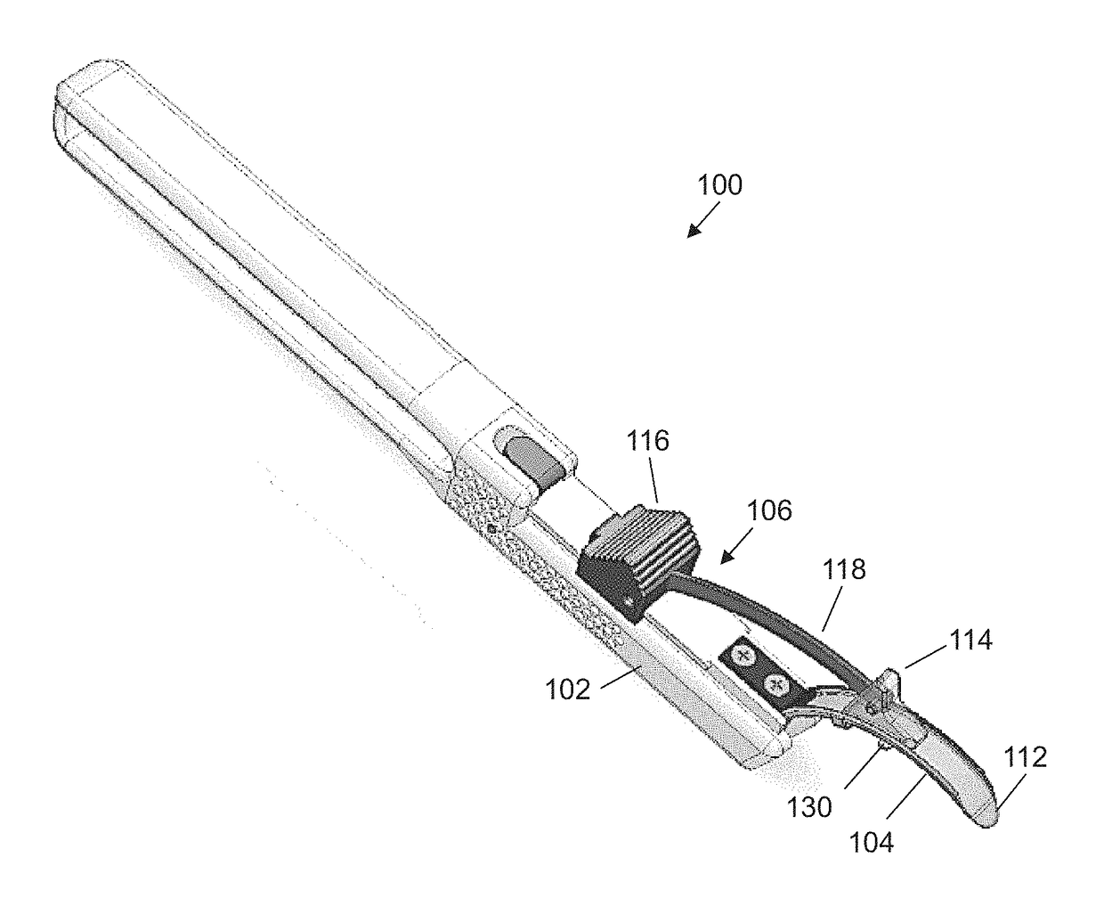
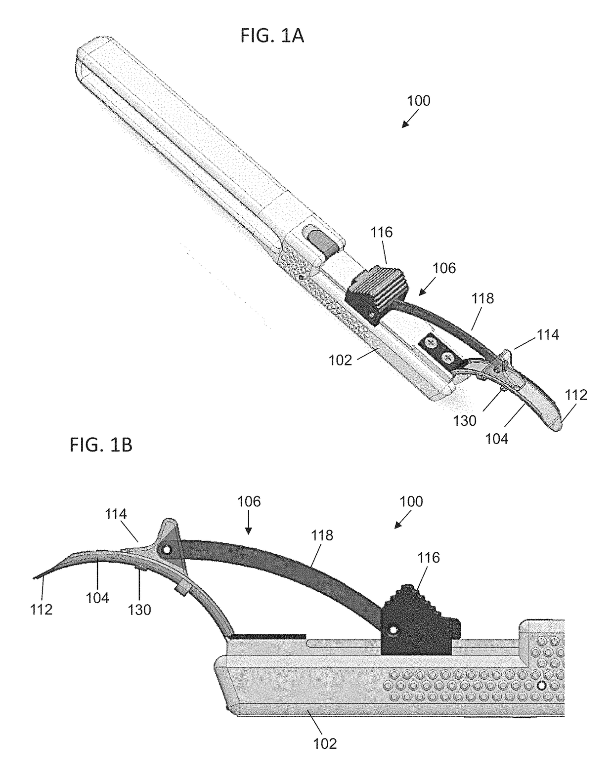
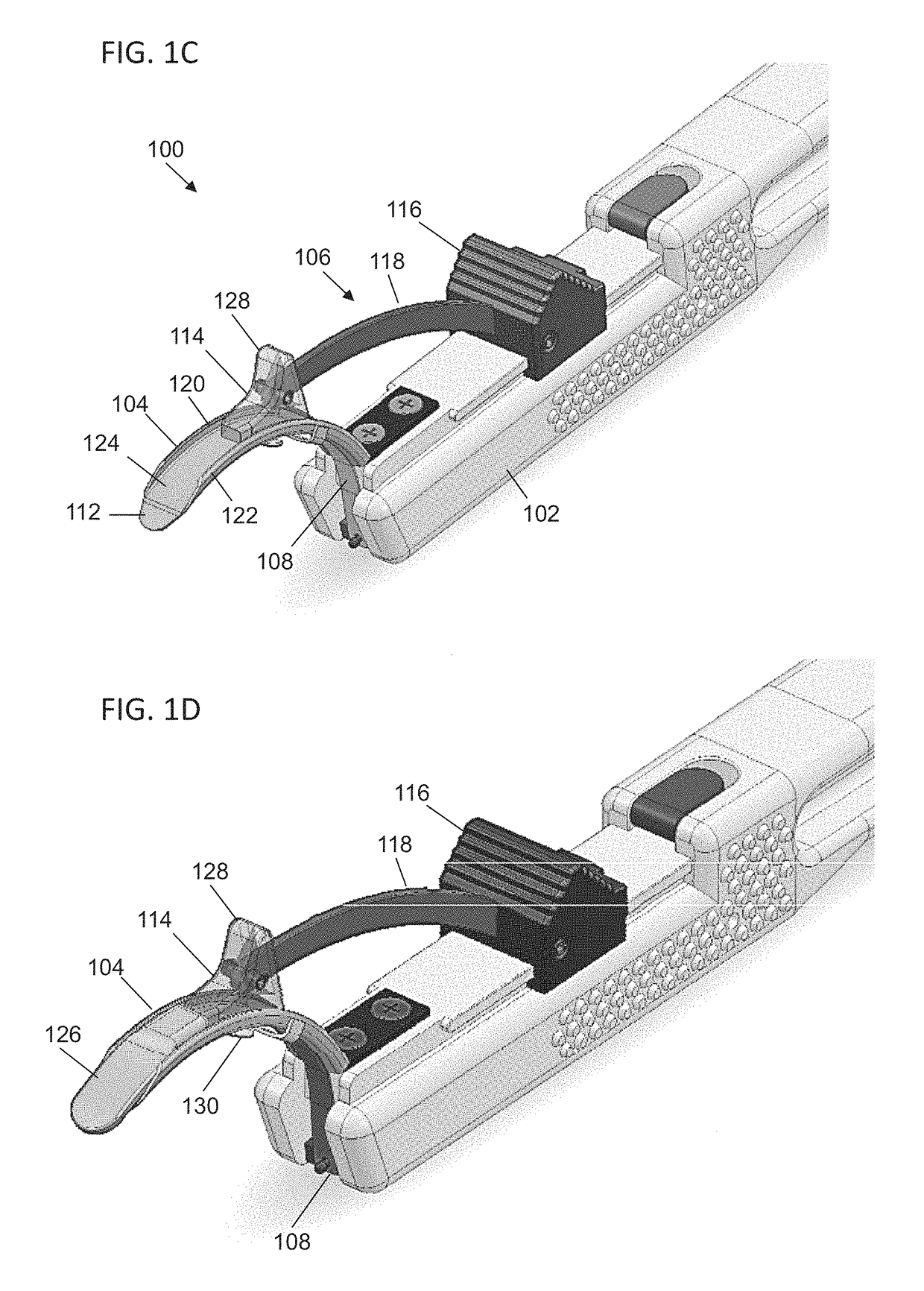
[0028]Described here are systems, devices, and methods for delivery of an implant into the orbit. Generally, the systems and devices may be configured to deliver one or more implants into tissue within the orbit (e.g., between the eyeball and the bones forming the orbit). Generally, the systems and devices described here may be used to form an opening in a tissue, such as the conjunctiva, to separate tissue beyond the opening to form a pocket in the tissue, and to deliver an implant into the pocket. The systems described here may include one or more devices configured to perform these steps. In some instances, the systems include a single device that performs all of the steps. In other instances, the system may include multiple devices which collectively perform these steps. The devices described here may be sterilizable (and in some instances, resterilizable), and may or may not be disposable (or partially disposable). Examples of these devices, systems, and methods will be describ...


PUM


Abstract

Systems, devices, and methods for delivering an implant to the orbit. In some instances, the systems may include a delivery device having a tongue member and a handle. The delivery device may further include an ejector configured to deliver an implant from the tongue member. The delivery device may also include a piercing member configured to create an opening in tissue. The systems may further include a piercing member for creating an opening in tissue. In some instances, the piercing member may have a first blade member rotatably connected to a second blade member.

Description

CROSS-REFERENCE TO RELATED APPLICATIONS[0001]This application claims priority to U.S. Provisional Patent Application Ser. No. 61 / 778,230, filed Mar. 12, 2013 and titled “IMPLANT DELIVERY DEVICES, SYSTEMS, AND METHODS” and to U.S. Provisional Patent Application Ser. No. 61 / 943,921, filed Feb. 24, 2014 and titled “IMPLANT DELIVERY DEVICES, SYSTEMS, AND METHODS,” the contents of each of which are hereby incorporated in its entirety.FIELD[0002]The present invention relates generally to systems, devices, and methods for delivering an implant to a portion of the anatomy such as the orbit.BACKGROUND[0003]Treatment methods for ocular conditions such as dry eye may require delivery of an implant or other device to the orbit of a patient. The orbit is a cavity of the skull that houses the eyeball and its nerves, muscles, and other appendages. The presence of these anatomical structures within the orbit, which in some instances may be easily damaged, can provide a limited working space for del...

Claims


Application Information

Patent Timeline
Patent Type & Authority Patents(United States)
IPC IPC(8): A61F9/007A61F9/00A61M31/00A61F2/14A61F2/16
CPCA61F9/007A61F9/0017A61F2/14A61F2/141A61F2/148A61F2/1662A61M31/007A61M2210/0612
Inventor KUZMA, JANUSZACKERMANN, DOUGLAS MICHAELSTIVERS, CHRISTOPHER WILLIAM
Owner OCULEVE
Why Eureka
Try Eureka