Rotary die cutter

a rotary die cutter and cylinder technology, applied in the direction of rotary presses, printing presses, printing presses, etc., can solve the problems of affecting the operation of the machine, the cylinder is not able to provide air blowing holes at a predetermined position on the magnet cylinder, and the cylinder is depressed or bending, so as to prevent the cylinder from depressing or bending or damage to the bearing

Inactive Publication Date: 2012-08-09
KOMORI CORP
View PDF4 Cites 18 Cited by
  • Summary
  • Abstract
  • Description
  • Claims
  • Application Information

AI Technical Summary

Benefits of technology

[0005]It is an object of the present invention to provide a rotary die cutter capable of preventing depression or bending of a cylinder or damage to a bearing due to factors associated with cut pieces adhering on a flexible die.
[0007]In the present invention, the rotary die cutter includes an air blowing device, guide device, and receiving device. The air blowing device blows air in nearly the tangential direction to the die cylinder in the period from when the die cylinder is opposed to the opposed cylinder first until they are opposed to each other next. The guide device guides cut pieces having their leading edges peeled by the air. The receiving device receives the cut pieces guided by the guide device. According to the present invention, even a flexible die type die cutter can reliably peel cut pieces adhering on a die plate to prevent depression or bending of a cylinder or damage to a bearing.

Problems solved by technology

In such a case, if the next material to be die-cut is supplied to the gap between a die cylinder and an anvil cylinder without removing these cut pieces, the two objects: the material to be die-cut and the cut pieces are stacked on each other in the gap between the die cylinder and the anvil cylinder, thus posing problems such as depression or bending of the cylinder or damage to a bearing.
Unfortunately, because a flexible die type rotary die cutter which fixes, by magnetic attraction, a thin flexible die including blade dies formed integrally with a magnet cylinder die-cuts cut pieces having various shapes, an air blowing hole cannot be provided at a predetermined position on the magnet cylinder in this machine.

Method used


Image

  • Rotary die cutter
  • Rotary die cutter
  • Rotary die cutter

Examples


Embodiment Construction

[0020]An embodiment according to the present invention will be described in detail below with reference to the accompanying drawings.

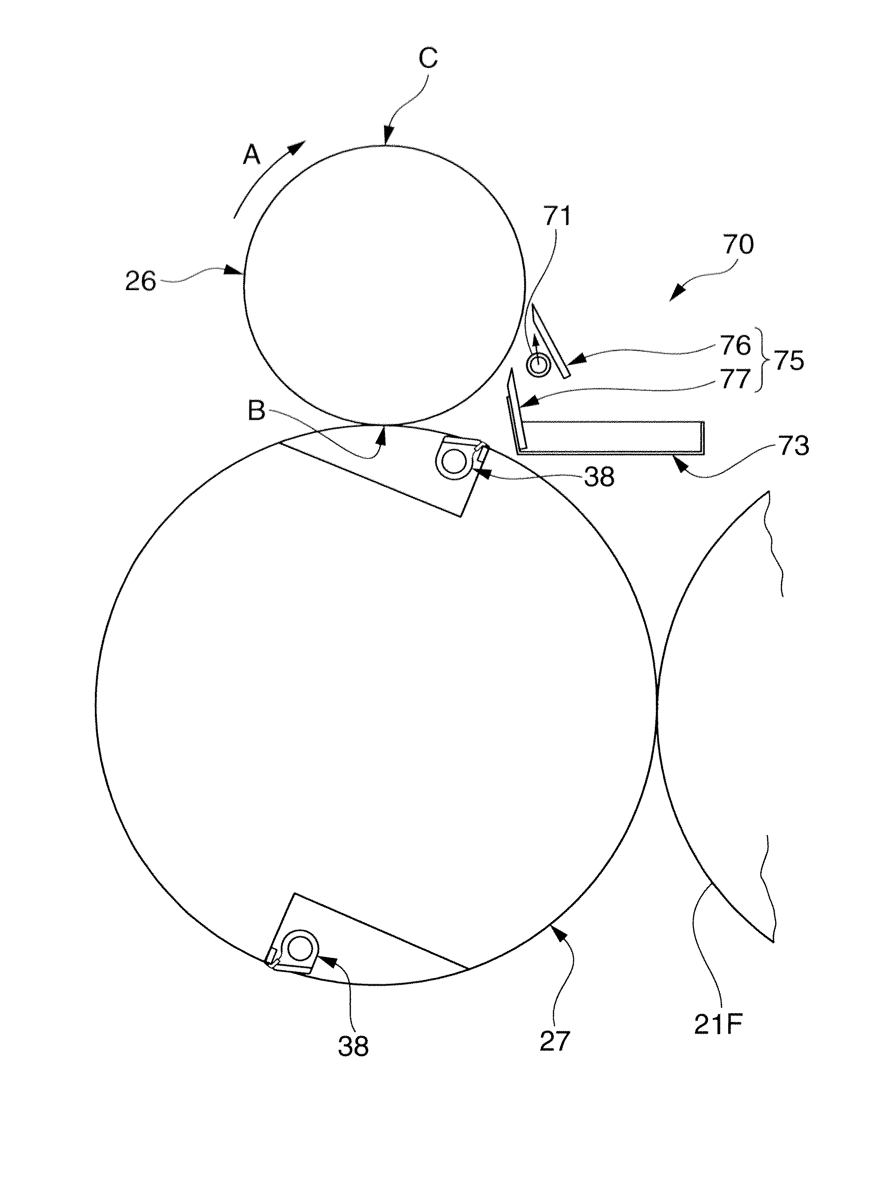
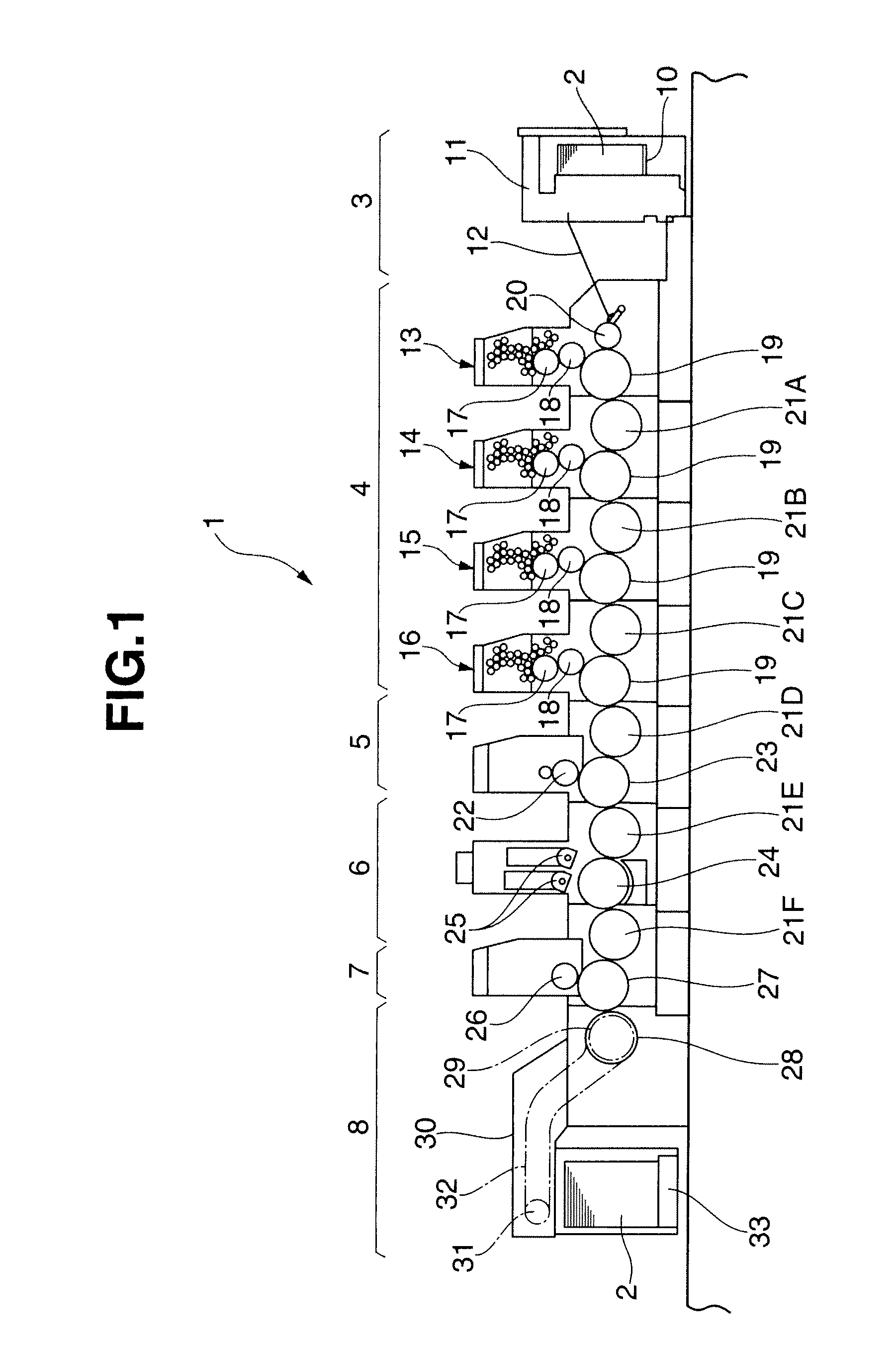
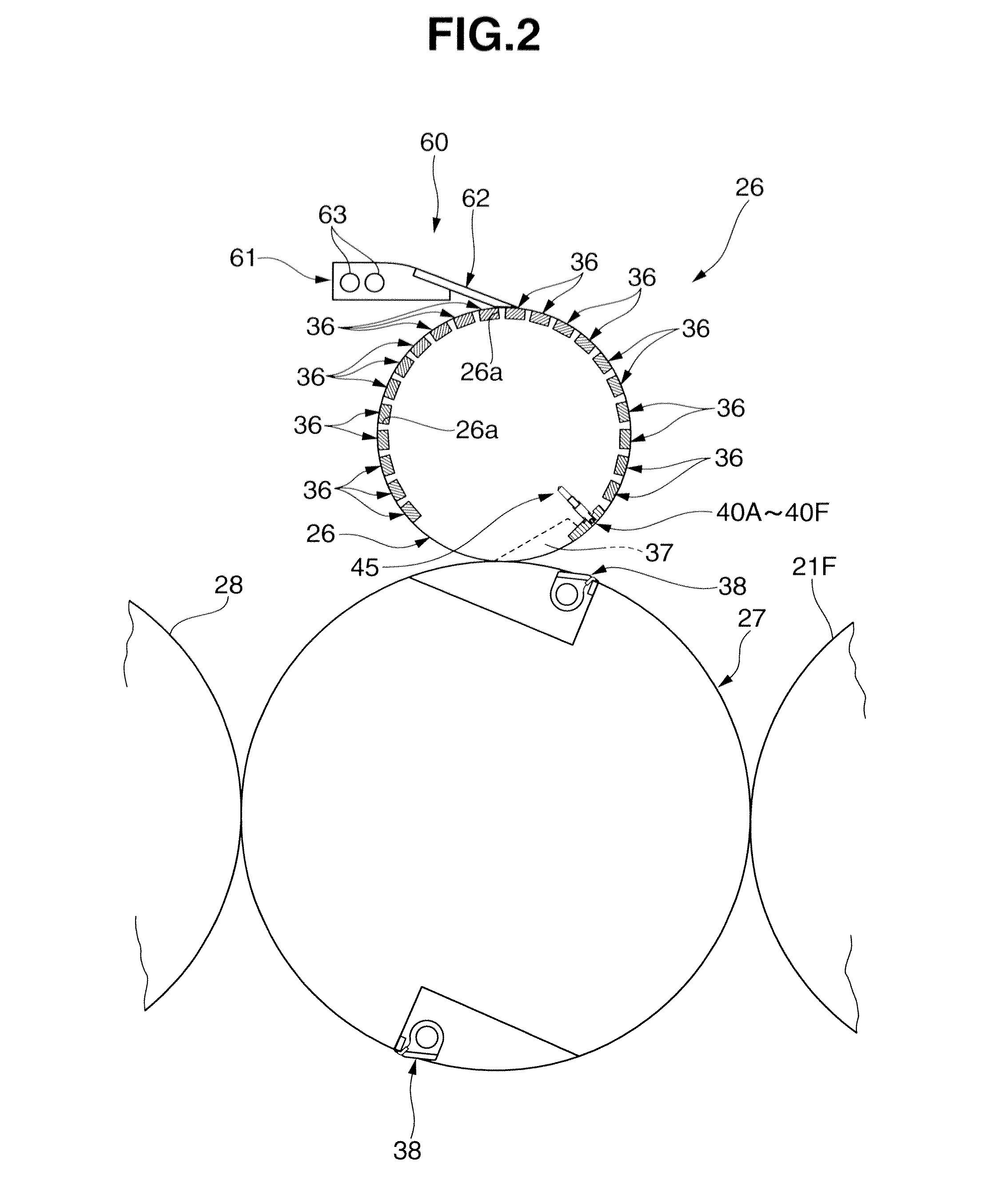
[0021]A sheet-fed offset rotary printing press 1 according to this embodiment includes a sheet feed device 3, printing device 4, coating unit 5, drying unit 6, flexible die type rotary die cutter 7, and sheet delivery device 8. The sheet feed device supplies sheets 2 serving as materials to be die-cut one by one. The printing device 4 prints on the sheets 2 supplied from the sheet feed device 3. The coating unit 5 coats varnish on the sheets 2 printed by the printing device 4. The drying unit 6 dries the sheets 2 coated with varnish by the coating unit 5. The rotary die cutter 7 performs hand push cutting of the sheets 2 dried by the drying unit 6 into a predetermined pattern. The sheet delivery device 8 delivers the cut sheets 2 having cut pieces.

[0022]The sheet feed device 3 includes a pile board (sheet stacking device) 10 and sheet feed unit (sheet ...


PUM

PropertyMeasurementUnit
angleaaaaaaaaaa
thickaaaaaaaaaa
thicknessaaaaaaaaaa

Abstract

A rotary die cutter including a die plate including a blade which die cuts a material, die cylinder, opposed cylinder, air blowing device, receiving device, and guide device. The die cylinder mounts the die plate on its circumferential surface and is supported rotatably. The opposed cylinder is opposed to the die cylinder and supported rotatably. The die cylinder cuts the material using the die plate at the position at which the die cylinder is opposed to the opposed cylinder. The air blowing device blows air onto the circumferential surface of the die cylinder in the tangential direction to the die cylinder from the downstream side to the upstream side in the direction in which the die cylinder rotates. The receiving device receives the cut piece peeled from the die plate by the air blown from the air blowing device. The guide device guides the cut piece to the receiving device.

Description

BACKGROUND OF THE INVENTION[0001]The present invention relates to a rotary g die cutter including a flexible die which is fixed on a die cylinder and has blade dies that cut a material to be die-cut, such as a sheet or a web, and, more particularly, to a flexible die type rotary die cutter including a flexible die fixed onto a magnet cylinder by magnetic attraction.[0002]Recently, a rotary die cutter for die-cutting only a necessary portion in a material to be die-cut, such as paper, corrugated cardboard, high polymer film, or rubber sheet has been presented. To die-cut a necessary portion, a rotary die cutter of this type die-cuts the necessary portion along its contour while leaving part of a material to be die-cut intact as joints. In such rotary die-cutting, it is often the case that the joints are torn from the material to be die-cut upon die-cutting, and cut pieces adhere onto the blade surfaces of cutting blades. In such a case, if the next material to be die-cut is supplied ...

Claims


Application Information

Patent Timeline
Patent Type & Authority Applications(United States)
IPC IPC(8): B26D7/18
CPCB26D7/1854B26D7/26B26D2007/0018B41F13/54B26F1/384B41F19/008B26D2007/2607Y10T83/2066
Inventor OHSAWA, SHIN
Owner KOMORI CORP
Why Eureka
Try Eureka