
Vehicle upper back panel structure

a technology for upper back panels and vehicles, which is applied in the direction of vehicle structures, child seats, superstructure sub-units, etc., can solve the problems of unsuitable suppression of vibration of upper back panels and cracks, and achieve the improvement of rigidity of speaker attachment portions, improved nv performance of upper back panels, and improved ease of forming

Active Publication Date: 2017-08-01
TOYOTA JIDOSHA KK
View PDF12 Cites 1 Cited by
  • Summary
  • Abstract
  • Description
  • Claims
  • Application Information

AI Technical Summary

Benefits of technology

[0007]The present disclosure provides a vehicle upper back panel structure that may improve NV performance of an upper back panel.

Problems solved by technology

However, in the configuration described in JP-A No. 2012-111308, since front-rear direction beads that increase the rigidity of the upper back panel and that extend along the vehicle front-rear direction in shapes protruding toward the vehicle upper side, are formed adjacent on both sides of the anchor member attached at the vehicle width direction center, vibration of the upper back panel may not be suitably suppressed.
In cases in which a flange is formed to least one out of the front end portion or the rear end portion of the front-rear direction bead by bending the upper back panel toward the vehicle lower side, generally, since displacement to the vehicle lower side to form the front-rear direction bead and displacement to the vehicle lower side to form the flange are concentrated in the at least one out of the front end portion or the rear end portion of the front-rear direction bead, cracks may occur at this position.

Method used


Image

  • Vehicle upper back panel structure
  • Vehicle upper back panel structure
  • Vehicle upper back panel structure

Examples


Embodiment Construction

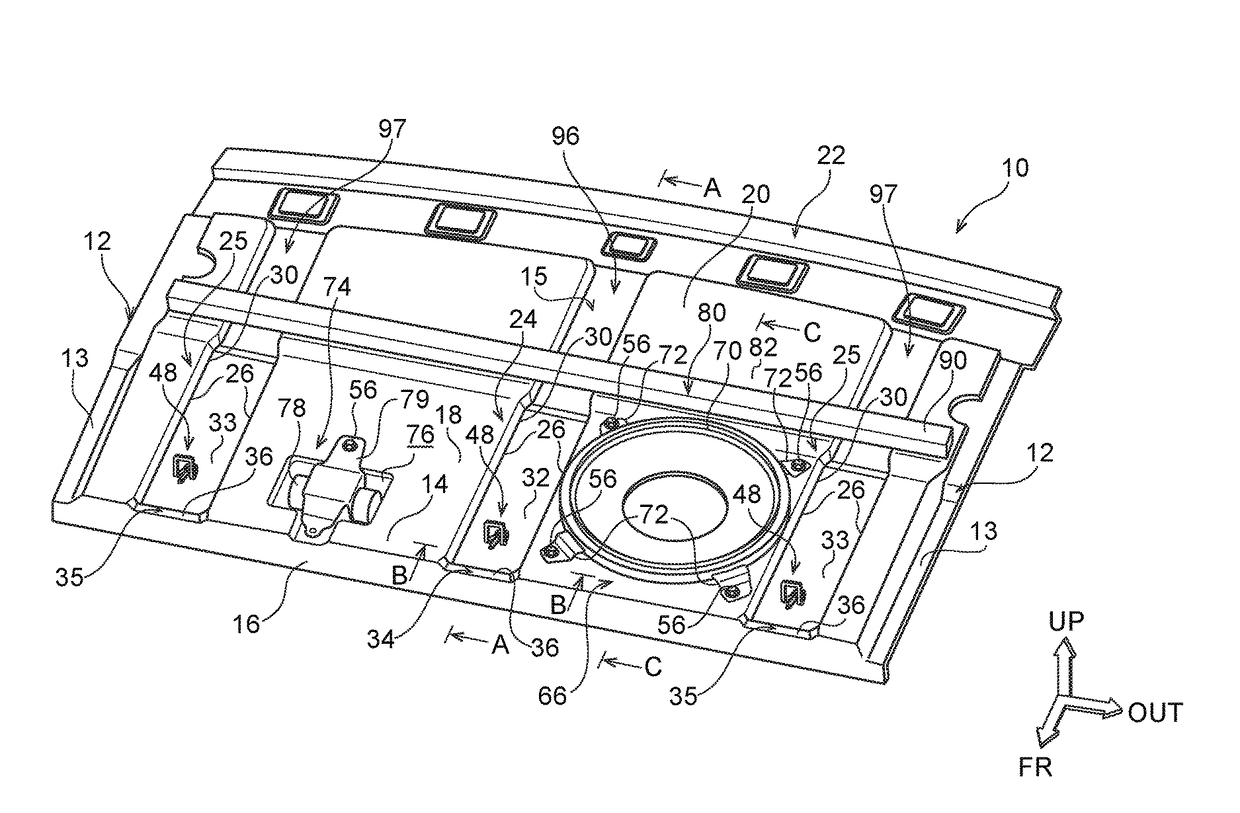
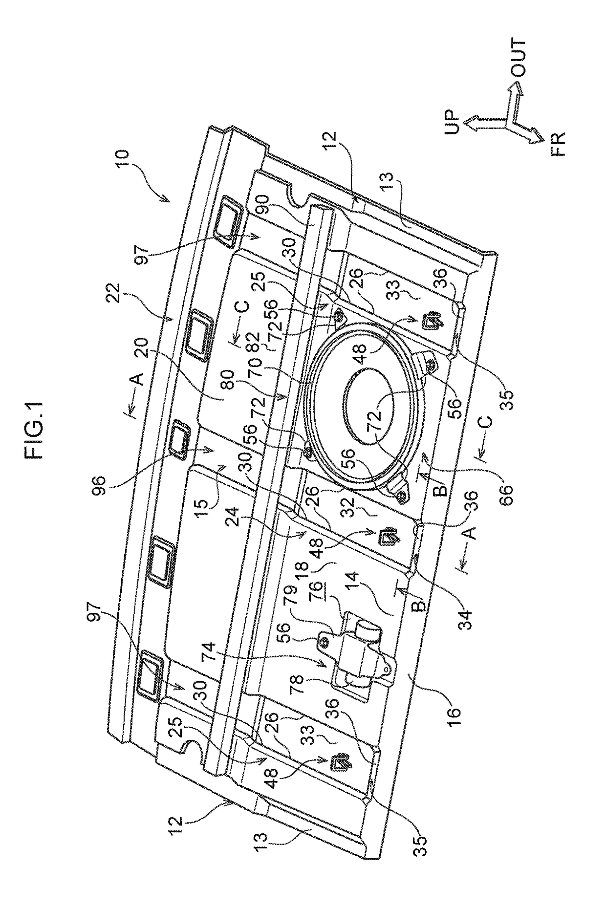
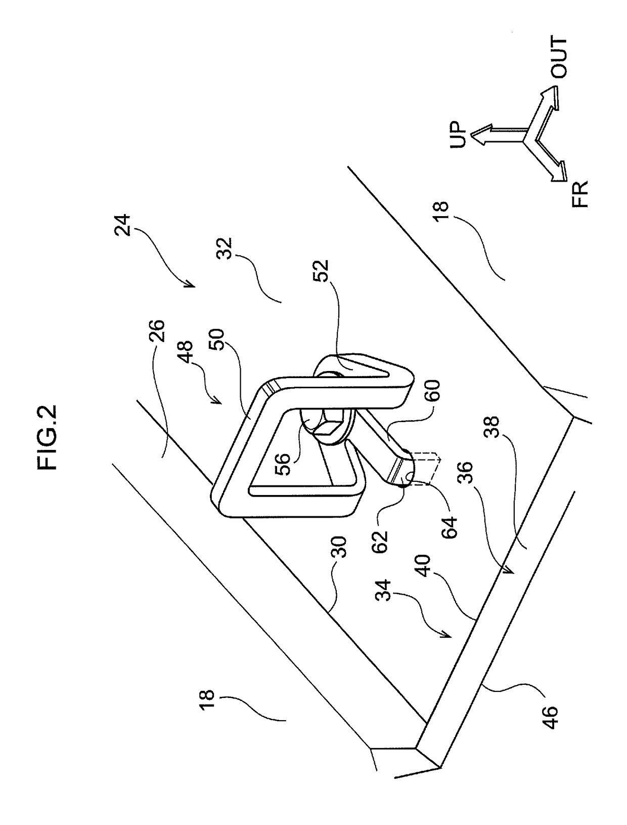
[0030]Explanation follows regarding a vehicle upper back panel structure according to a first exemplary embodiment, with reference to FIG. 1 to FIG. 5. In the drawings, the arrow FR indicates the vehicle front-rear direction front side, the arrow OUT indicates the vehicle width direction outside, and the arrow UP indicates the vehicle up-down direction upper side.

[0031]As illustrated in FIG. 1, an upper back panel 10 is provided in a vehicle rear section (not illustrated). The upper back panel 10 is formed in a rectangular plate shape in plan view of the vehicle, and is disposed with its length direction along the vehicle width direction. The upper back panel 10 is joined by welding to rear pillar inner panels or the like (not illustrated), at fixing portions 13 formed to end portions 12 on both vehicle width direction sides of the upper back panel 10. Accordingly, the vehicle compartment and a luggage compartment are partitioned by the upper back panel 10. Note that the upper back ...


PUM


Abstract

The present disclosure provides a vehicle upper back panel structure including: an upper back panel, provided at a rear section of a vehicle, that is formed in a rectangular plate shape with a length direction along a vehicle width direction in vehicle plan view, that is fixed to a vehicle body at end portions on both vehicle width direction sides by respective fixing portions, and that includes a horizontal wall section disposed horizontally between the fixing portions; and a front-rear direction bead that is formed continuously along a vehicle front-rear direction from a front end portion to a rear end portion of the horizontal wall section of the upper back panel, at a position including a central portion in the vehicle width direction between one of the fixing portions and the other of the fixing portions of the upper back panel.

Description

CROSS-REFERENCE TO RELATED APPLICATION[0001]This application claims priority under 35 USC 119 from Japanese Patent Application No. 2015-026757, filed on Feb. 13, 2015, the disclosure of which is incorporated by reference herein.BACKGROUND[0002]Technical Field[0003]The present disclosure relates to a vehicle upper back panel structure.[0004]Related Art[0005]Japanese Patent Application Laid-Open (JP-A) No. 2012-111308 describes an upper back panel (rear parcel shelf) structure. Specifically, an upper back panel that is installed to a rear section of a vehicle, partitions between a vehicle compartment and a luggage compartment. The upper back panel includes: a horizontal wall section disposed substantially horizontally; a speaker attachment hole for attaching a speaker; an anchor member disposed in front of the speaker attachment hole and for anchoring an anchor member of a child seat, and a patch provided at peripheral edges of the speaker attachment opening. A bead extending along th...

Claims


Application Information

Patent Timeline
Patent Type & Authority Patents(United States)
IPC IPC(8): B60R11/00B60R11/02B60N2/28B60R13/02
CPCB60R11/0217B60N2/2887B60R13/0268B60R2013/0287B60N2/2809
Inventor KATO, HIROYUKI
Owner TOYOTA JIDOSHA KK
Learn More