Coaxial connector

a technology of coaxial connectors and connectors, applied in the direction of coupling bases/cases, coupling device connections, two-part coupling devices, etc., can solve the problems of poor inter-modulation distortion characteristics, occupy a lot of space, and the spatial utilization of space is not further advanced, so as to improve the user's operational convenience, improve the connection characteristics, and improve the performance of the pim

Active Publication Date: 2017-08-08
SOLID
View PDF14 Cites 1 Cited by
  • Summary
  • Abstract
  • Description
  • Claims
  • Application Information

AI Technical Summary

Benefits of technology

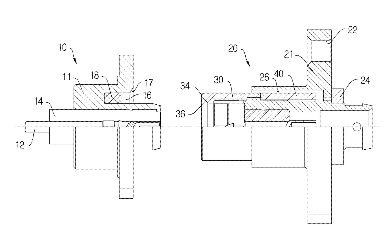
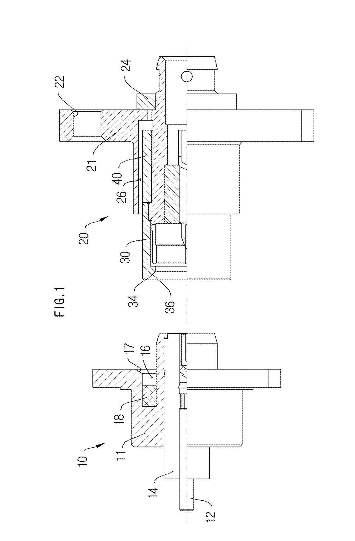
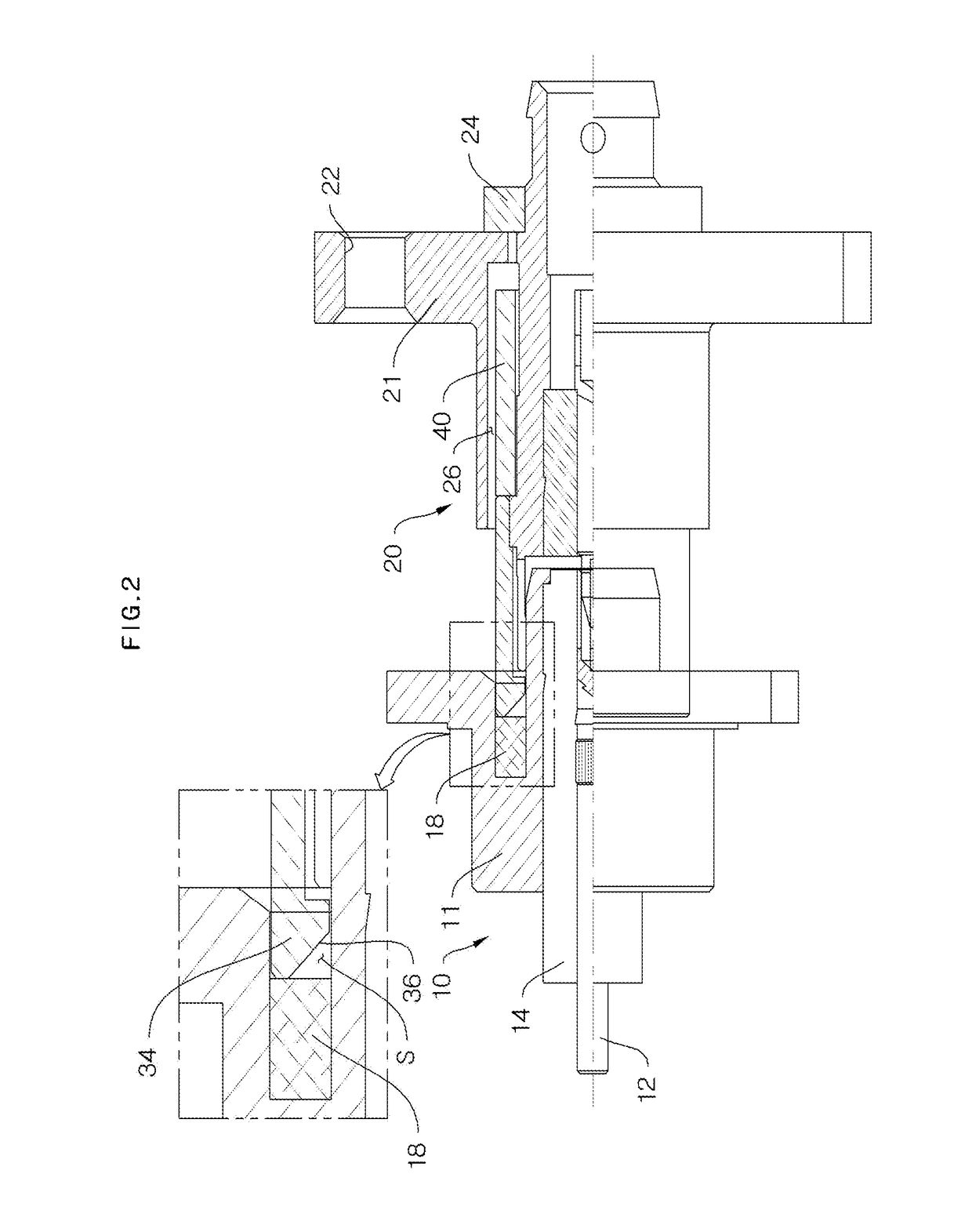
[0014]According to the present invention, it is possible to obtain an improved PIM performance by improved connection characteristics between the first connector and the second connector coupled through the conductive gasket, and at the same time, it is possible to improve the user's operational convenience by solving the spatial issue.
[0015]Also, since it is possible to compensate for the assembly tolerances in the process in which the second connector is coupled by a bushing or an elastic member, coupling between the first connector and the second connector can be softly and tightly performed.

Problems solved by technology

However, it has a problem of bad inter-modulation distortion characteristics (hereinafter, referred to as PIM).
Meanwhile, the N-type has excellent PIM characteristics, but since it has a larger size than the SMA type, it will occupy a lot of space, and there is also a need to spend a wider space for tightening.
Although the DIN type also has the most excellent PIM characteristics, the spatial utilization is not further easier due to an increase in size as much.
However, it has a problem that occupies a lot of space as described above.
Also, as decreases in the weight / size of the communication devices progress, spatial issues caused by conventional thread-fastening type connectors have become more sensitive matters, and have caused inconveniences to be used on the user side.
For example, in an ICS repeater, the interference between the forward and reverse signals generated in the apparatus gives a very sensitive affect on the ICS performance of the device.
However, in the case of the plug-in connector, since the isolation characteristics are greatly lower than the thread-fastening type connector, for some of the connections between modules, there are restrictions on the application, and thus, it has not been possible to solve the spatial problems and the inconvenience for use.

Method used


Image

  • Coaxial connector
  • Coaxial connector
  • Coaxial connector

Examples


Embodiment Construction

[0020]Exemplary embodiments of the present invention will be described below in more detail with reference to the accompanying drawings. The present invention may, however, be embodied in different forms and should not be construed as limited to the embodiments set forth herein. Rather, these embodiments are provided so that this disclosure will be thorough and complete, and will fully convey the scope of the present invention to those skilled in the art. Throughout the disclosure, like reference numerals refer to like parts throughout the various figures and embodiments of the present invention.

[0021]The terms used in this application are used to merely describe particular embodiments, and are not intended to limit the present invention. Expressions of the singular numbers include the expressions of the plural numbers unless they are obviously differently expressed in the context. In the present application, it should be understood that the terms, such as “comprising” or “having” a...


PUM


Abstract

The present invention relates to a coaxial connector. According to the present invention, there is provided a coaxial connector which is installed for electrical connection of a communication module, and includes a first connector in which an insulator through which a conductor penetrates is installed inside a first housing, and a conductive gasket is seated between the first housing and the insulator; and a second connector which is coupled so that a front end comes into close contact with the conductive gasket.

Description

TECHNICAL FIELD[0001]The present invention relates to a coaxial connector, and more particularly, to a coaxial connector having a structure in which connection characteristics between a first connector and a second connector are improved and improved PIM performance can be obtained.BACKGROUND ART[0002]As a method for interfacing RF input / output signals in a communication device with each other, a SMA type connector, an N type connector, a DIN type connector and the like are widely used. Usually, one of such common connectors is selectively used in consideration of the size and the RF output power. Since the SMA type has a small size, it occupies less space and it is easily fastened even in a narrow space. However, it has a problem of bad inter-modulation distortion characteristics (hereinafter, referred to as PIM). Meanwhile, the N-type has excellent PIM characteristics, but since it has a larger size than the SMA type, it will occupy a lot of space, and there is also a need to spen...

Claims


Application Information

Patent Timeline
Patent Type & Authority Patents(United States)
IPC IPC(8): H01R24/40H01R24/38H01R13/508H01R13/52H01R103/00
CPCH01R24/38H01R13/508H01R13/5219H01R24/40H01R2103/00
Inventor LEE, DONG WON
Owner SOLID
Why Eureka
Try Eureka