

Pullout guide
a pullout guide and guide technology, applied in the field of pullout guides, can solve the problems that the sequence control of the pullout guide cannot be implemented, the catch force cannot be vaguely determined, etc., and achieve the effect of high functional reliability
- Summary
- Abstract
- Description
- Claims
- Application Information
AI Technical Summary
Benefits of technology
Problems solved by technology
Method used
Image

Examples
Embodiment Construction
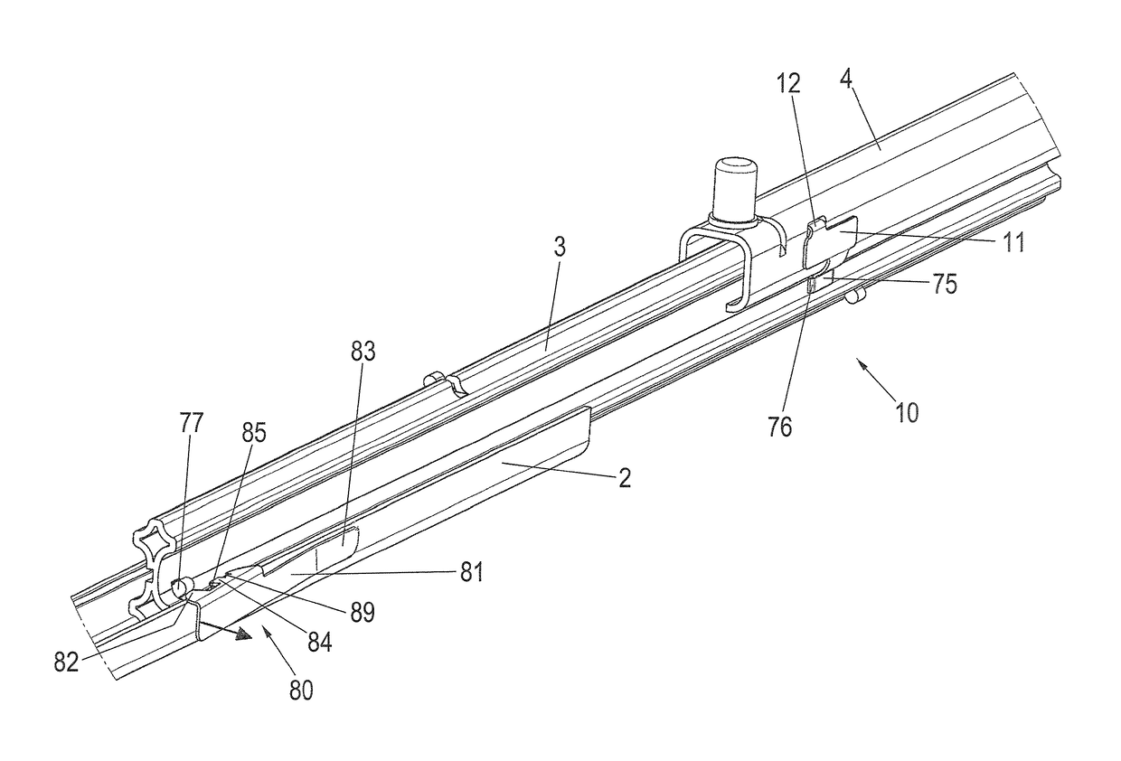
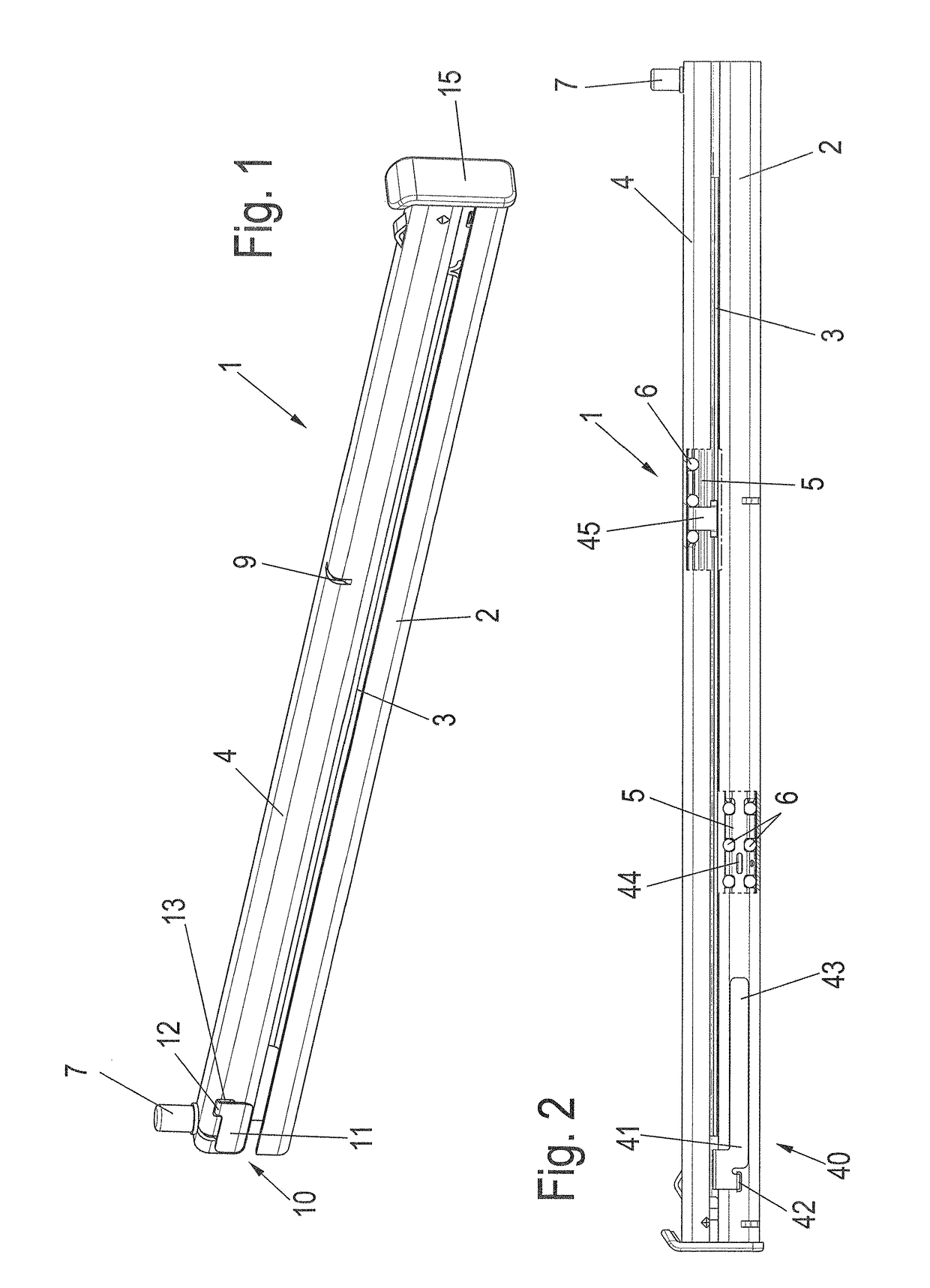
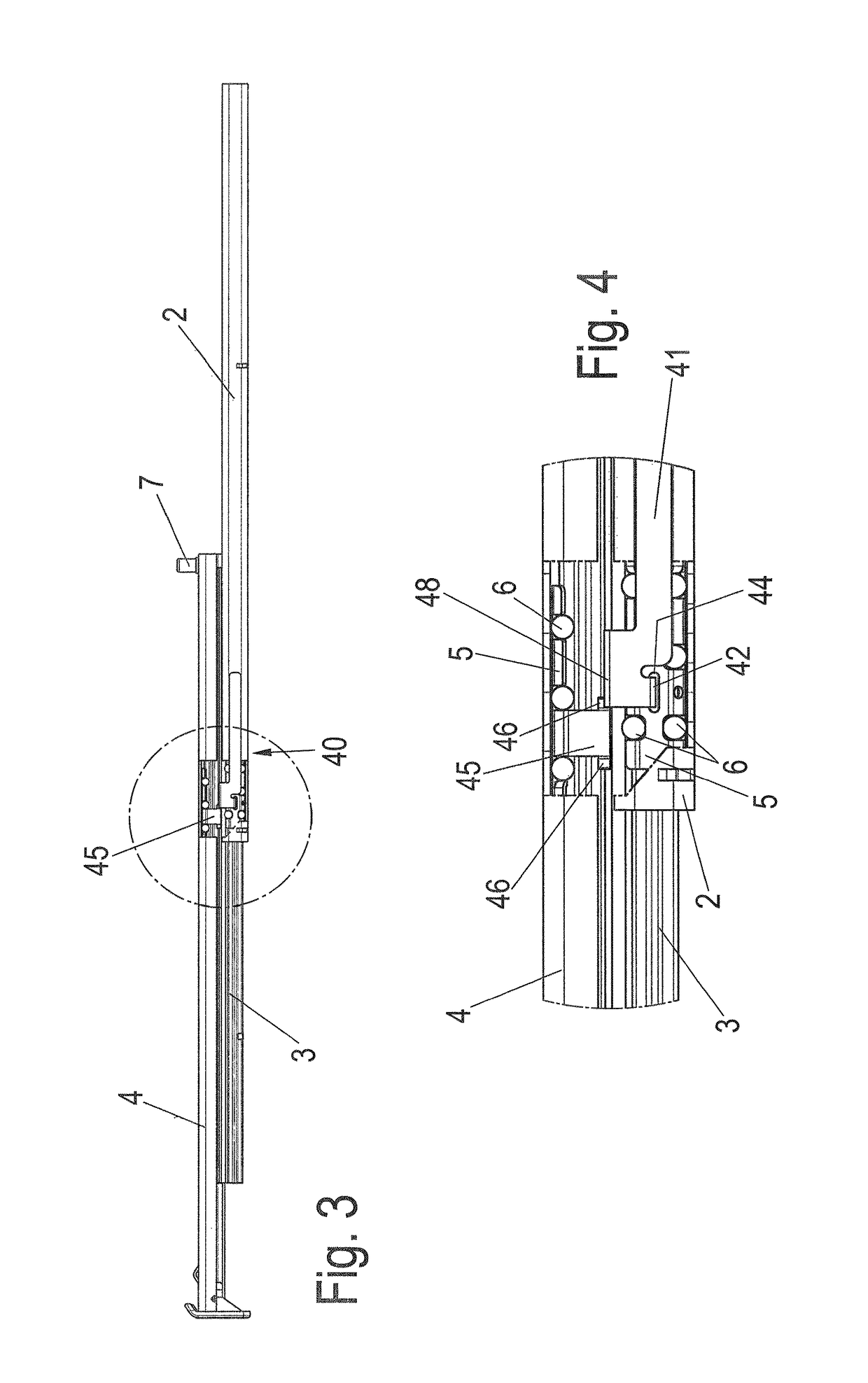
[0041]A pullout guide 1 comprises a first rail 2, which can be fixed on a body of a piece of furniture or a domestic appliance, and which is usually arranged in a stationary manner, a second rail 3, which is implemented as a middle rail, and a third rail 4, which is also referred to as a slide rail, on which thrust elements, such as drawers, cooked material carriers, or other components can be mounted so they are movable. A plug 7, which protrudes upward on the third rail 4, is used for mounting a thrust element, for example, a cooked material carrier, while a plate 15 is fixed on the first rail 4 on the opposing front side.
[0042]As shown in FIG. 1, a catch mechanism 10 having a bendable spring element 11, which engages with a projection 12 through an opening 13 in the first rail 4, is located on the third rail 4. The projection 12 protrudes inward from the rail 4 and presses therein behind a spherical roller body 6 on a roller body cage 5. During the movement of the third rail 4, t...
PUM
 Abstract
Description
Claims
Application Information