Valve, especially a pressure control valve

a valve and pressure control technology, applied in the direction of fluid pressure control, servomotors, instruments, etc., can solve the problems of vibration damage, and achieve the effect of stable behavior

Inactive Publication Date: 2004-08-24
HYDAC FLUITECHNIK GMBH
View PDF15 Cites 26 Cited by
  • Summary
  • Abstract
  • Description
  • Claims
  • Application Information

AI Technical Summary

Benefits of technology

Objects of the present invention are to provide improved valves with more stable behavior, in particula

Problems solved by technology

This flow also results in dampin

Method used


Image

  • Valve, especially a pressure control valve
  • Valve, especially a pressure control valve
  • Valve, especially a pressure control valve

Examples


Embodiment Construction

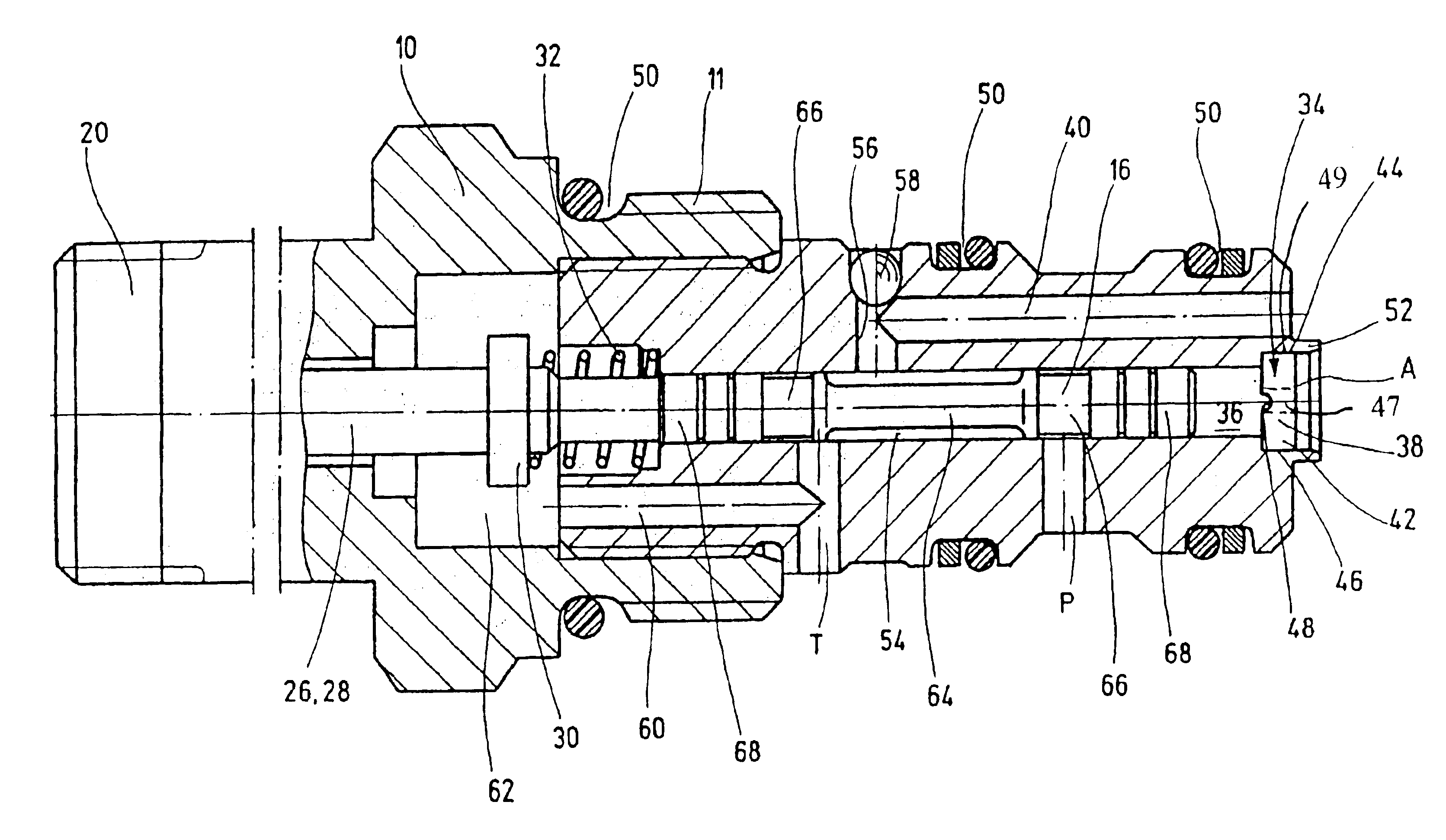
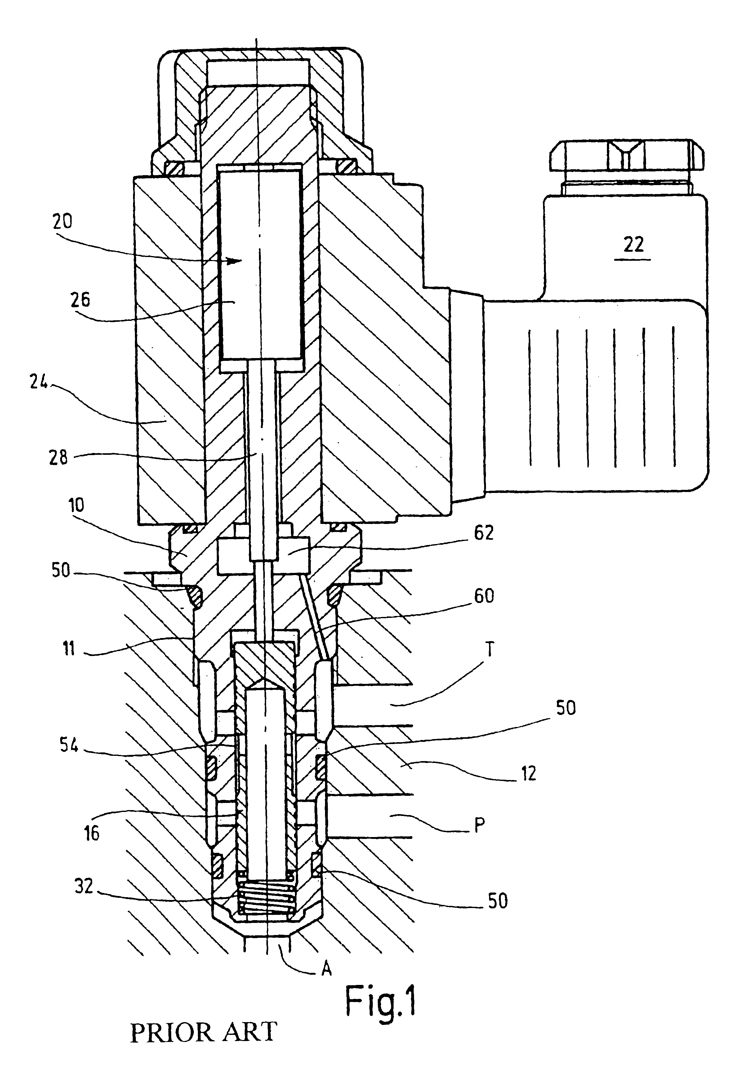
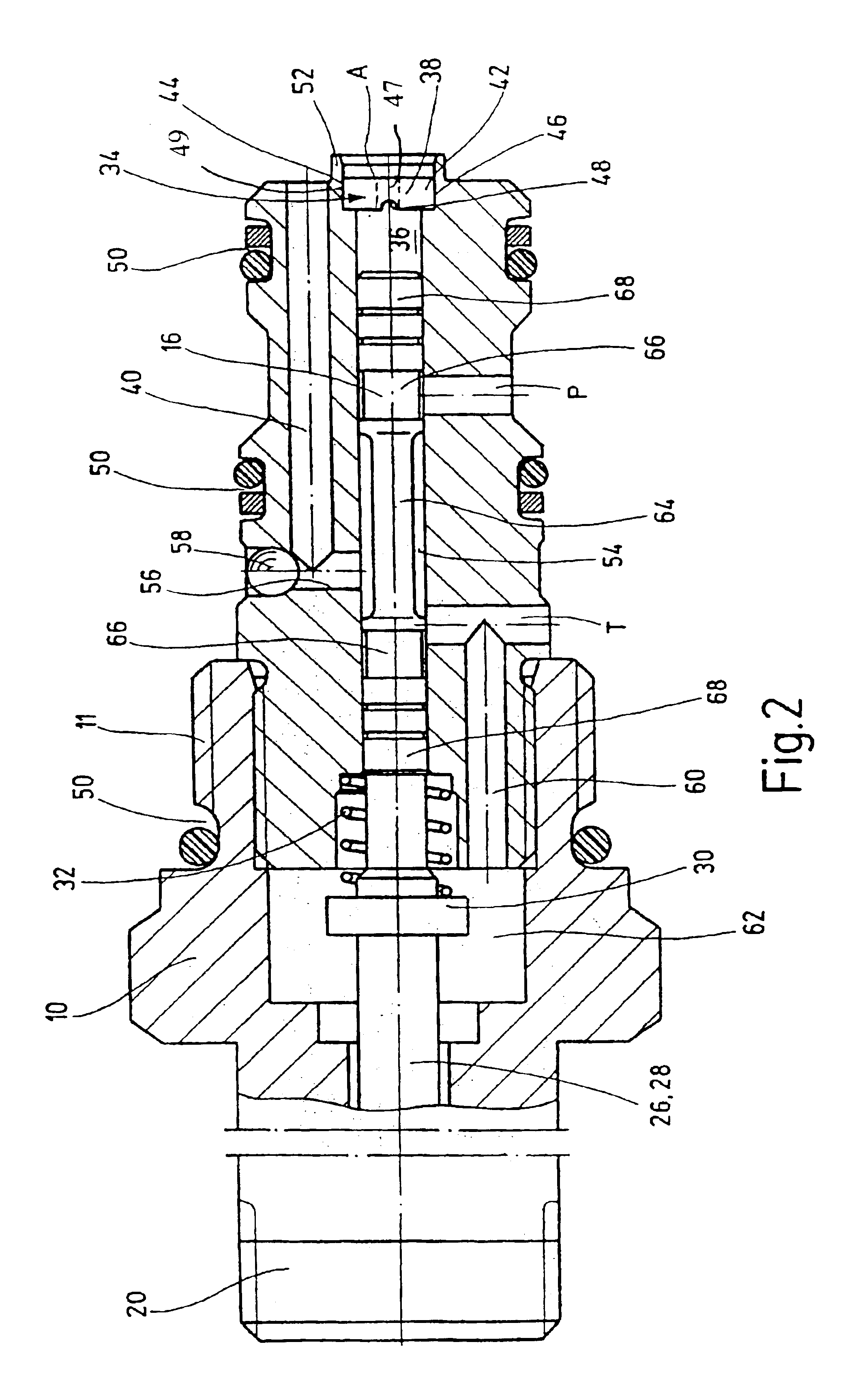
For better understanding of the valve of the invention, a conventional proportional pressure control valve is described in detail with reference to FIG. 1.

The conventional valve shown in FIG. 1 includes a valve housing 10 in the form of a screw-insertion cartridge, also designated as a cartridge valve. The conventional valve is screwed or threaded into a valve receptacle 12 with its fluid connections P, T, and A, by way of external threading 11. A is the appliance connection. P is the pump connection. T is the tank connection. The main or valve piston 16 extends longitudinally inside the valve housing 10, and is suitably hardened and ground. A magnet system 20, for electric actuation of the piston, includes a circuit box 22 and a controllable magneto inductor 26 introduced into a magnetic coil 24. The magneto inductor 26 is connected to the valve piston 16 by a tappet-like actuating element 28. The front end of element 28 rests on a resetting or pressure spring 32, specifically, in ...


PUM


Abstract

A valve, especially a pressure control valve, includes a housing (10) with a pump connection (P), an appliance connection (A) and a tank connection (T). A piston (16) controlled by a magnet armature (26) is guided inside the housing (10) of the valve. The vavle is provided with a hydraulic damping device (34) having a damping chamber (36) in fluid communication with appliance connection (A) through a throttle (38). The pump connection (P) or the tank connection (T) is selectively joined to the appliance connection (A) via a connecting line (40) according to the position of the piston (16). This valve improves upon known control valves so that the control valve remains stable in terms of behavior, especially with regard to permanent oscilliations.

Description

FIELD OF THE INVENTIONThe present invention relates to a valve, a pressure control valve in particular, with a valve housing having pump, appliance and tank connections. A valve piston can be driven by a magnetic inductor for guided movement within the valve housing.BACKGROUND OF THE INVENTIONConventional proportional pressure control valves are used, among other things, as control valves for oil-hydraulic systems to deliver a more or less constant output pressure with variable input pressure. The output pressure to be controlled is assigned by the current signal delivered by suitable triggering electronics and acting on an actuating magnet. The actuating magnet may be designed as a pressure sealed oil bath magnet with a long service life.Proportional pressure control valves serving this purpose may be directly controlled piston valves of a three-way design, that is, with pressure protection on the output side. They are employed, among other things, in oil-hydraulic systems to contr...

Claims


Application Information

Patent Timeline
IPC IPC(8): G05D16/20G05D16/02F16K11/07G05D16/10
CPCG05D16/2013G05D16/2024Y10T137/86622
Inventor BRUCK, PETERHILLESHEIM, THORSTEN
Owner HYDAC FLUITECHNIK GMBH
Why Eureka
Try Eureka