Patient bed system

a bed system and patient technology, applied in the field of patient bed systems, can solve the problem of requiring a relatively large amount of space for arrangemen

Active Publication Date: 2007-05-17
MAQUET GMBH
View PDF67 Cites 27 Cited by
  • Summary
  • Abstract
  • Description
  • Claims
  • Application Information

AI Technical Summary

Benefits of technology

[0014] In order to ensure a satisfactory and as far as possible constraint-free transfer of the bed from the trolley onto the column, and vice versa, the coupling elements should be aligned exactly with one another before transfer, so that they can slide one into the other, as far as possible free of constraint. This presupposes that the column head, which, of course, as a rule, can be adjusted to vary the position of the patient on an operating table, is in an exactly defined position in relation to the floor of the operating theatre on which the trolley stands. Also, for any reason, the position of the patient bed on the trolley may not be exactly parallel to the floor of the operating theatre. Since these deviations sometimes cannot be detected or cannot so quickly be detected by the naked eye, it is proposed, according to the invention, that at least one of the coupling elements located on the support-column side has provided ...

Problems solved by technology

Since the coupling elements have to absorb a high load and are therefore of corre...

Method used


Image

  • Patient bed system
  • Patient bed system
  • Patient bed system

Examples


Embodiment Construction

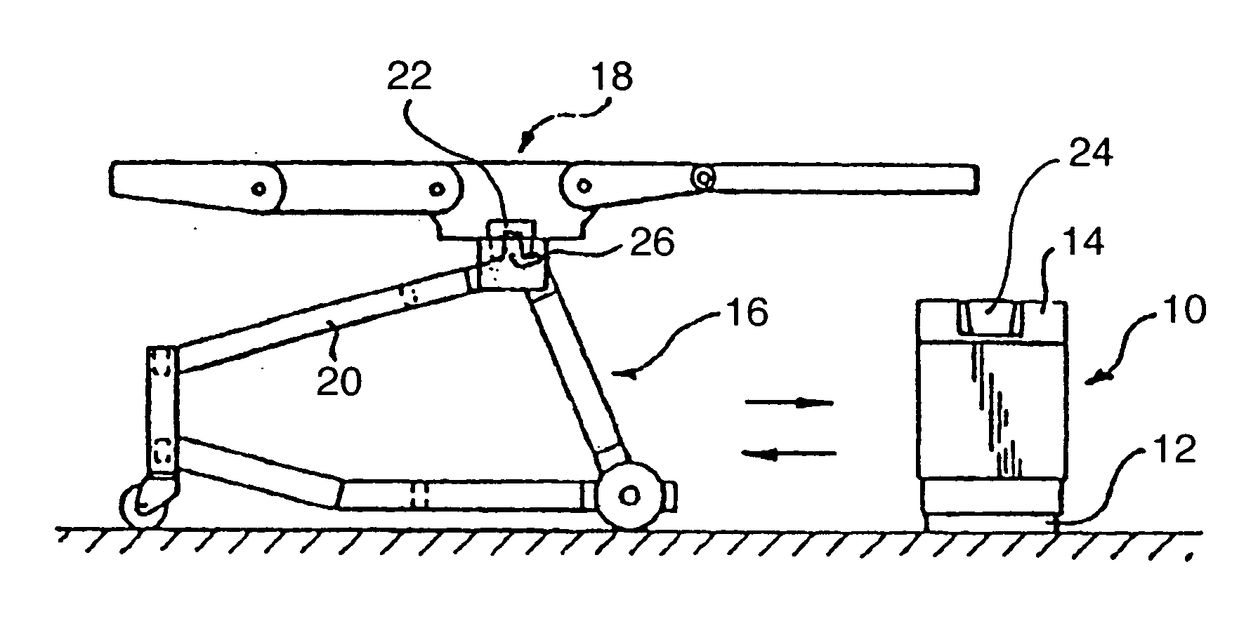
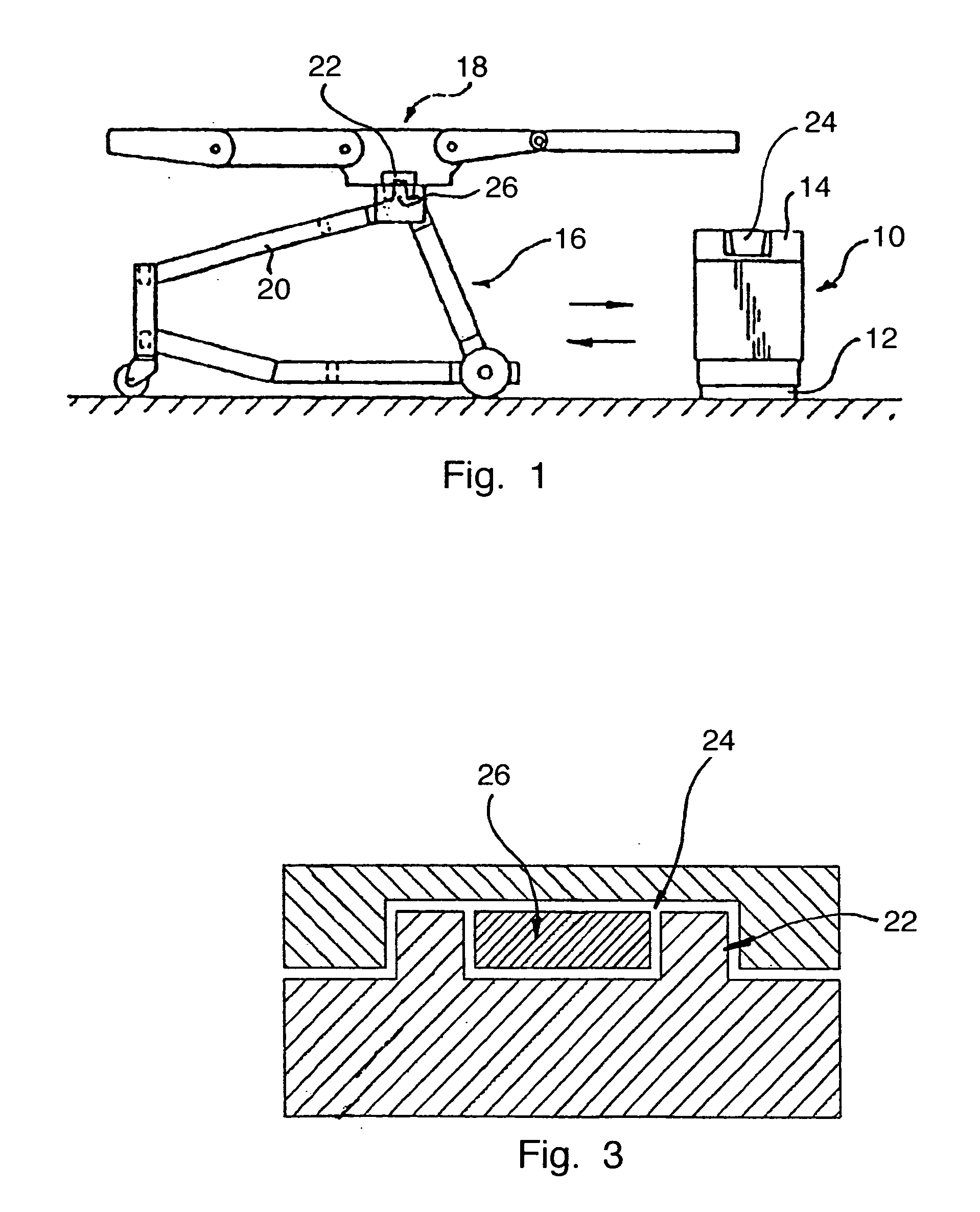
[0023] The patient bed system, illustrated diagrammatically in FIG. 1, comprises a support column, designated in general by 10, of an operating table, with a column foot 12 and with a column head 14 mounted vertically adjustably on the latter. The height adjustment device is not illustrated. It may be designed in any conventional way. As a rule, this may be a hydraulic or mechanical lifting device.

[0024] Located on the left, next to the support column, is a trolley, designated in general by 16, which carries a bed or table board 18 of the operating table. The trolley 16 comprises two side frame parts 20 which are connected to one another by means of crosspieces, not illustrated, as is illustrated in EP 457 246 B1. The trolley 16 can be moved up to the support column 10 such that the latter lies between the side frame parts 20.

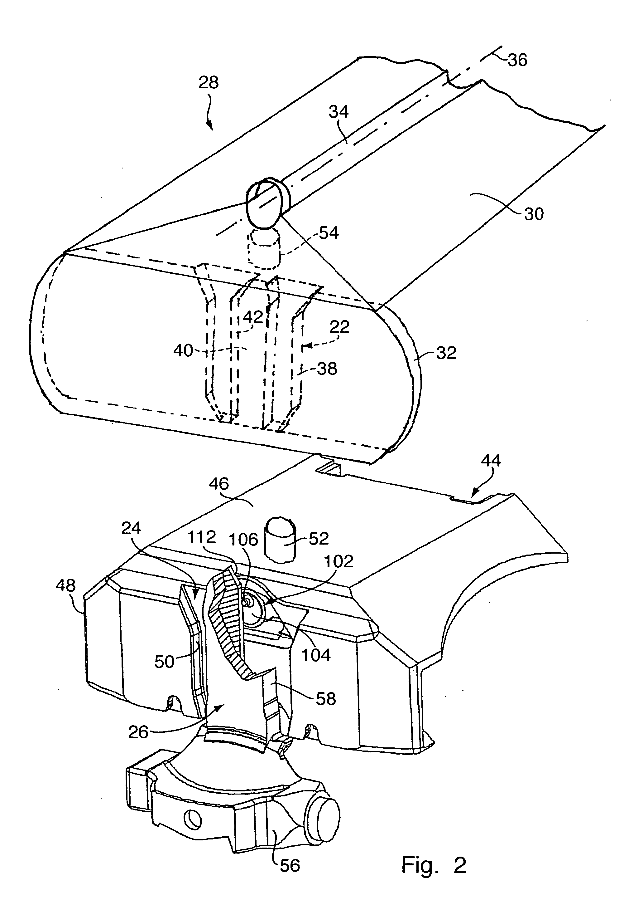
[0025] On the longitudinal side edges of the bed 18, first coupling elements 22 are arranged, which are intended for engagement into second coupling elements...


PUM


Abstract

In a patient bed system, comprising a patient bed, a support column for supporting the bed and a trolley for transporting the bed, the bed having arranged on it first coupling elements (22) which are intended for selective connection to second or third coupling elements (24, 26) on the support column and on the trolley respectively, the first coupling elements (22) have in each case an outer contour (38) and a clearance (40) with an inner contour (42), the second or the third coupling elements (24, 26) being designed in each case as guide tenons which have an outer contour (58) adapted to the inner contour (42) of the clearance (40) of the first coupling elements (22) and which are intended for engagement into the clearance (40), and the third or the second coupling elements (26, 24) having in each case a clearance intended for receiving a first coupling element (22) and having an inner contour (50) adapted to the outer contour (38) of the first coupling elements (22).

Description

CROSS REFERENCE TO RELATED APPLICATIONS [0001] Applicant hereby claims foreign priority benefits under U.S.C. § 119 from German Patent Application No. 10 2005 054 224.7 filed on Nov. 14, 2005, the contents of which are incorporated by reference herein. FIELD OF THE INVENTION [0002] The invention relates to a patient bed system, comprising a patient bed, a support column for supporting the bed and a trolley for transporting the bed, the bed having arranged on it first coupling elements which are intended for selective connection to second or third coupling elements on the column and on the trolley respectively. BACKGROUND OF THE INVENTION [0003] Such a system is known, for example, from EP 457 246 B1. To transfer the bed onto the trolley, the latter is brought into a suitable position in relation to the support column. By means of the downward movement of the height adjustment device of the support column, the bed is first lowered, until it lies on the trolley. At the moment of trans...

Claims


Application Information

Patent Timeline
IPC IPC(8): A61G7/08
CPCA61G7/1019A61G7/1046A61G7/1057A61G7/1065A61G13/00A61G2203/40A61G2203/80A61G7/05A61G7/00A61G7/002A61G7/018
Inventor KOCH, GUIDO
Owner MAQUET GMBH
Why Eureka
Try Eureka