Plug-in coupling

a plug-in coupling and coupling technology, applied in the direction of couplings, hose connections, cable terminations, etc., can solve the problems of preventing unable to establish the required tight connection and/or ensure the required functional reliability, etc., to prevent the risk of the sealing element being pushed or squeezed, and the effect of high functional reliability

Inactive Publication Date: 2008-07-29
FRIATEC AG
View PDF23 Cites 27 Cited by
  • Summary
  • Abstract
  • Description
  • Claims
  • Application Information

AI Technical Summary

Benefits of technology

[0005]Another object of the invention is to provide a plug-in coupling with which a connection to at least one pipe end can be made with little effort and with a high functional reliability.
[0021]Furthermore with the plug-in coupling according to this invention, the clamping ring is arranged axially between the area of the annular groove with the sealing element and said end face or stop face. Furthermore in a particular embodiment of this invention, the wall of the annular groove accommodating the sealing element said wall being arranged at a distance from the free end of the base body, is designed as an undercut in which the sealing element is clamped when the pipe end is inserted. This prevents the sealing element from being forced out of the annular groove when the pipe end is inserted.

Problems solved by technology

If the pipe end is not inserted coaxially with the longitudinal axis of the plug-in coupling into the annular gap between the base body but instead is inserted at a greater or lesser angle to the longitudinal axis of the plug-in coupling, there is a risk that the sealing element will be forced at least partially out of the annular groove or damaged so that the required tight connection cannot be established and / or assured with the required functional reliability.

Method used


Image

  • Plug-in coupling
  • Plug-in coupling
  • Plug-in coupling

Examples


Embodiment Construction

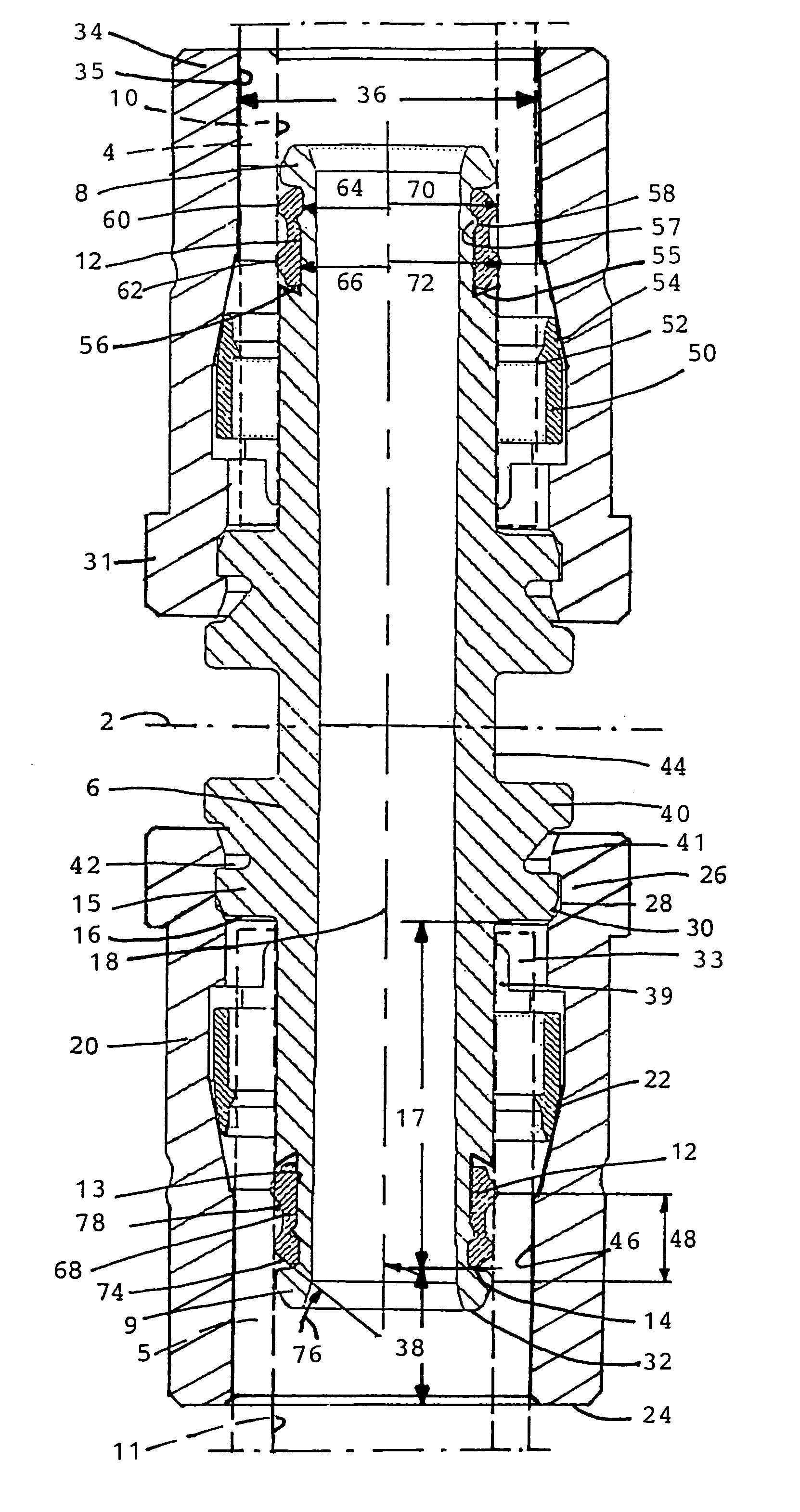
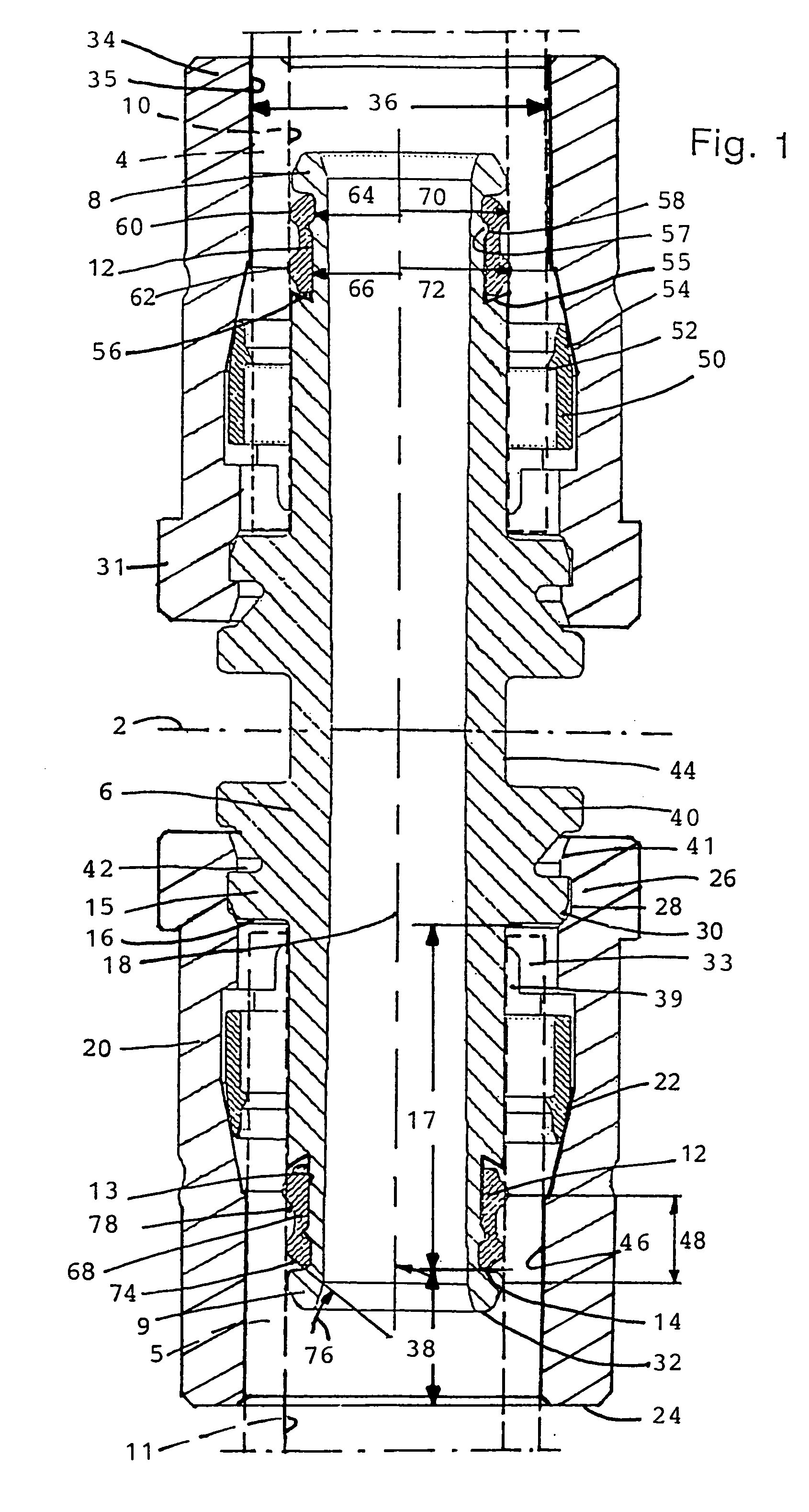
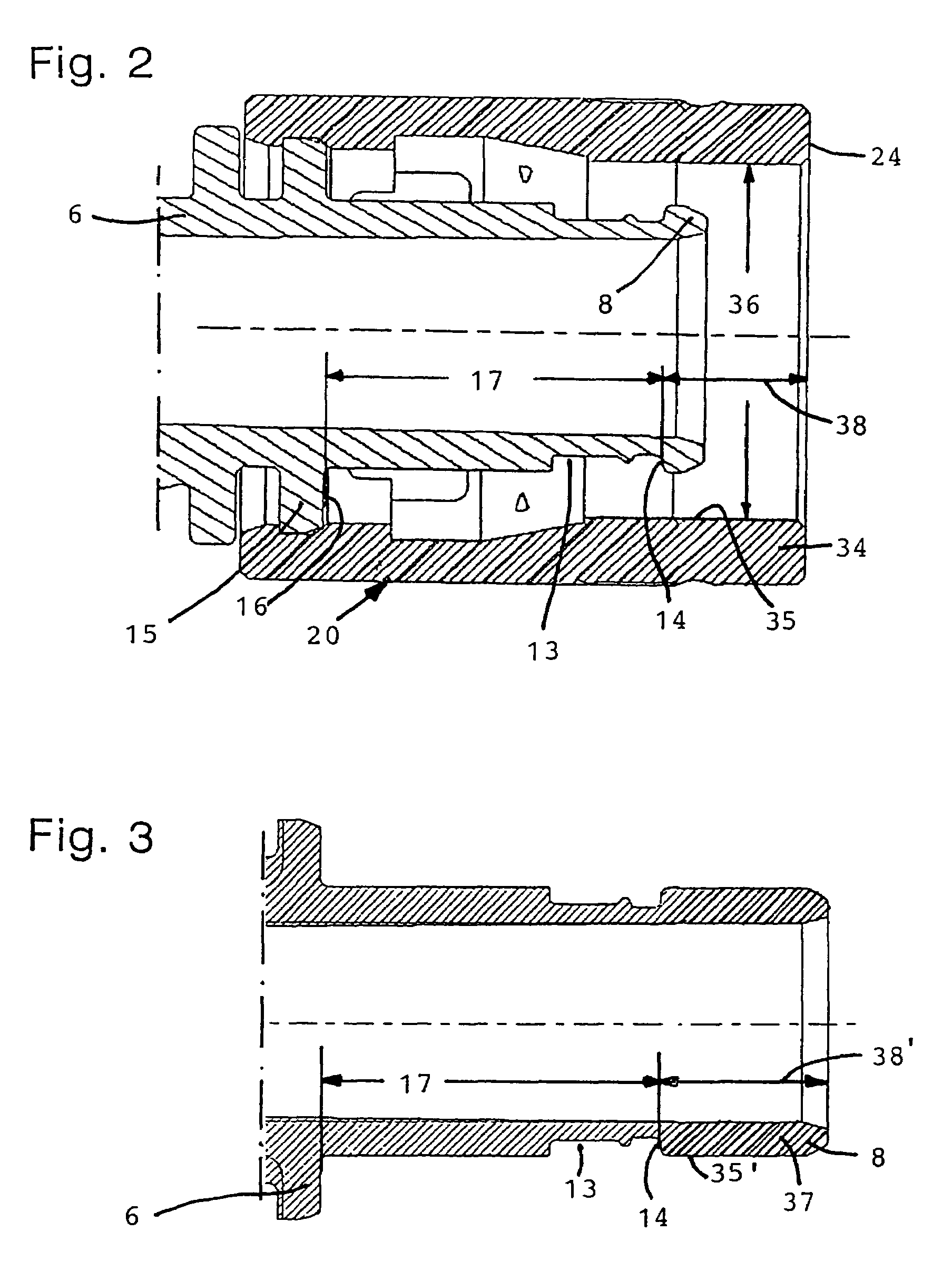
[0030]The plug-in coupling according to FIG. 1 is constructed as a double socket which is symmetrical with the middle plane 2 and serves to join the two pipe ends 4, 5, which are indicated schematically. This double socket thus contains two parts, one each on the left and right of the middle plane 2, each separately forming a plug-in coupling according to the invention. The following discussion applies accordingly to the two symmetrical parts of the double socket shown here.

[0031]The double socket, i.e., the plug-in coupling, comprises a base body 6 which is partially inserted into the two pipe ends 4, 5, the end areas 8, 9 of the base body 6 preferably being constructed as conical enlargements which extend radially from the free ends of the base body 6 to the outside in the direction of the inside surfaces 10, 11 of the particular pipe end 4, 5 and extend radially outward. A sealing element 12 is in sealing contact with the respective inside surface 10, 11 and is situated in an ann...


PUM

PropertyMeasurementUnit
chamfer angleaaaaaaaaaa

Abstract

A plug-in connector comprising a base body (6), an annular sealing element (12), a clamping ring (50) and an annular body (20) which can be connected to the base body (6). A pipe end (4, 5) against which the sealing element (12) is arranged in a sealing manner, can be secured in the plug-in connector by the clamping ring (50). The plug-in connector of the invention can be connected to an end (4, 5) of at least one pipe in a simple manner and with a high degree of functional reliability, excluding the risk of assembly errors. For this purpose, the sealing ring (12) is arranged in an annular groove (14) of the base body (6) and comprises two sealing beads (60, 62) which are situated against the inner surface of the inserted pipe end (4, 5) in the manner of two o-ring seals.

Description

CROSS REFERENCE TO RELATED APPLICATIONS[0001]This application is a continuation of international patent application no. PCT / EP02 / 13002, filed Nov. 20, 2002 designating the United States of America and published in German as WO 03 / 046429 A1, the entire disclosure of which is incorporated herein by reference. Priority is claimed based on Federal Republic of Germany patent application nos. DE 101 58 208.0, filed Nov. 28, 2001; DE 102 17 127.0, filed Apr. 17, 2002, and DE 102 21 971.0, filed May 17, 2002.BACKGROUND OF THE INVENTION[0002]This invention relates to a plug-in coupling comprising a base body, an annular sealing element, a clamping ring and an annular body which is connectable to the base body, in which a pipe end can be fixedly secured in sealing contact with the sealing element in the plug-in coupling by the clamping ring.[0003]Published international patent application no. WO 00 / 75 554 A1 discloses a plug-in coupling of this type which is constructed as a double socket and...

Claims


Application Information

Patent Timeline
Patent Type & Authority Patents(United States)
IPC IPC(8): F16L33/20F16L17/025F16L21/02F16J15/10F16L21/08F16L33/22F16L37/092
CPCF16L37/0925F16L33/227
Inventor BAVING, HANS-JUERGENMANNWEILER, GUDRUNMILNAZIK, PEERSCHIEDHERING, LARSZELLER, HENRIK
Owner FRIATEC AG
Why Eureka
Try Eureka