Steering column for a motor vehicle

a technology for steering columns and motor vehicles, applied in the direction of steering parts, vehicle components, transportation and packaging, etc., can solve the problems of large structural space occupied, complex and correspondingly cost-intensive, and reduce manufacturing expenditures and costs, and achieve the effect of reducing manufacturing costs and costs, increasing operational safety, and reducing structural spa

Active Publication Date: 2018-02-22
THYSSENKRUPP PRESTA AG +1
View PDF2 Cites 24 Cited by
  • Summary
  • Abstract
  • Description
  • Claims
  • Application Information

AI Technical Summary

Benefits of technology

[0013]A particular advantage of the invention is that at least the said two, and possibly more, energy absorption elements can be combined structurally in an energy absorption device according to the invention into an integrated unit, which, as a whole, can be mounted on one side of the casing tube or the steering column. By the combination into an integrated unit, components can, in comparison to the separate design known in the prior art, be spared, e.g., mounting elements for connecting the energy absorption elements to the engagement part and the inner casing tube. The manufacture expenditures and costs can be reduced thereby. In addition, a particularly compact construction of an energy absorption device with two or more crash degrees is made possible, which construction requires a smaller amount of structural space than in the prior art.
[0014]An advantageous embodiment of the invention provides that the first and the second energy absorption elements be arranged in a radial direction with respect to the longitudinal axis in a sandwich-like manner, one above the other, or one adjacent to the other. In this construction, two or more energy absorption elements are arranged in the form of a stack, one above the other, or one next to the other, and form a particularly compact assembly.
[0015]Alternatively, it is also conceivable and possible that two or more energy absorption elements be arranged one behind the other in the direction of the longitudinal axis. A smaller structural height in the radial direction can be realized thereby.
[0016]Preferably, the at least two energy absorption elements are arranged in a common housing. The housing forms a part of the energy absorption device according to the invention, which part encloses the energy absorption elements at least partially and protects them against disturbances. Furthermore, mounting elements for the energy absorption elements, longitudinal guides for the engagement part, and the like can be formed in or on the housing.
[0017]In an advantageous construction, a separating element is arranged between the energy absorption elements. A separating element can, for example, be formed by a separating wall or a separating plate inserted between adjacent energy absorption elements. As a result, adjacent energy absorption elements are shielded against each other in a functionally reliable manner, so that the function of an energy absorption element cannot be affected by adjacent energy absorption elements. This proves advantageous for increased operational safety and functional reliability.
[0018]One embodiment of the invention provides that at least one of the energy absorption elements be designed as an elongated bending element, which has two legs connected to each other by way of a bend, wherein the one leg can be affixed to the engagement part, and the other leg can be supported in the longitudinal direction on the inner casing tube. It is known to use as an energy absorption element a bending wire or binding strip that is designed to be U-shaped by means of a bend of approximately 180°, wherein the legs extend substantially parallel to the longitudinal direction, wherein the term “substantially parallel” means a deviation with a solid angle of ±10°. The end of the one leg is connected to the inner casing tube with respect to a movement in the longitudinal direction—for example, by being supported on a stop or counter bearing in the event of a crash. The other end is connected to the engagement part for coupling-in, e.g., by inserting a pin-shaped coupling element or carrier, which carries said end in the longitudinal direction in the event of a crash. In a relative displacement of the two ends in the event of a crash, the bend moves across the longitudinal extent of the bending element, wherein kinetic energy is converted or absorbed by the deformation work. According to the invention, two or more elongated bending elements can be arranged as described above in the radial direction in the form of a stack, one above the other.

Problems solved by technology

Disadvantageous in the previously known energy absorption device is, however, that the individual energy absorption elements are arranged on respective separate mounting units on opposite sides of the inner casing tube.
As a result, a relatively large structural space is taken up, which limits the flexibility in the integration into a vehicle body.
On the other hand, the manufacture and separate mounting of at least two energy absorption elements, including the respectively required mounting means, are complex and correspondingly cost-intensive, due to the high number of required components.

Method used


Image

  • Steering column for a motor vehicle
  • Steering column for a motor vehicle
  • Steering column for a motor vehicle

Examples


Embodiment Construction

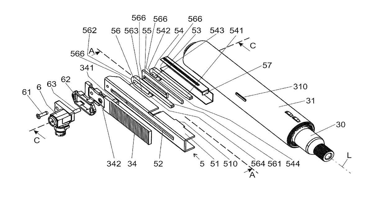
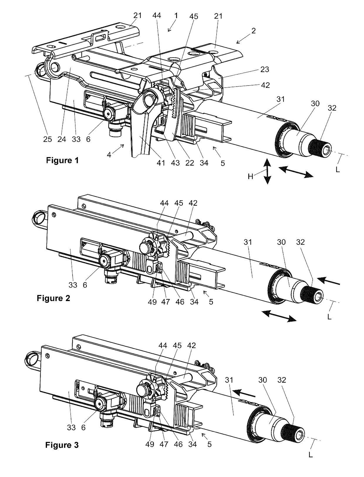
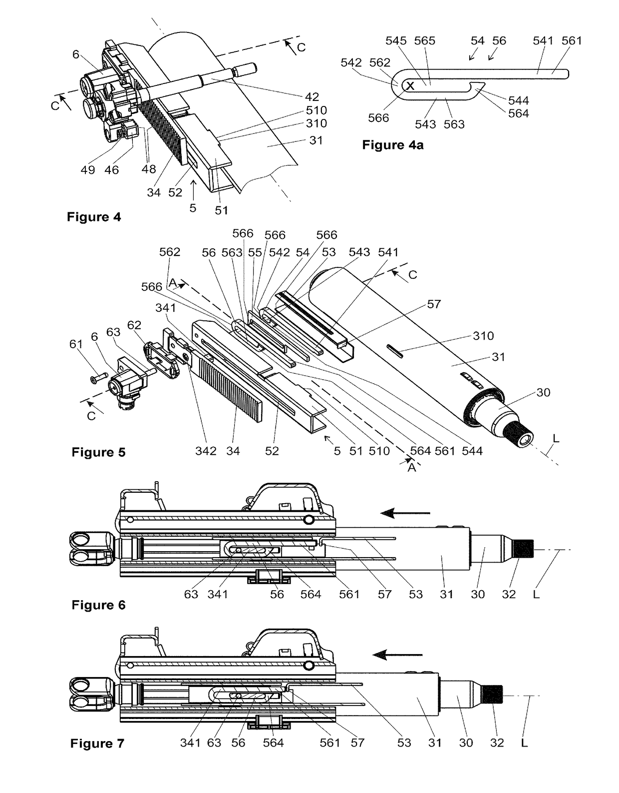
[0010]In order to solve the aforementioned problem, the invention proposes to arrange the first and second energy absorption elements in a radial direction with respect to the longitudinal axis on the same side of the inner casing tube.

[0011]According to the invention, the first and second energy absorption elements are not arranged, as in the prior art, at separate positions on different sides of the casing tube, but combined on a single side of the inner casing tube. In other words, the at least two energy absorption devices previously required for the realization of different crash degrees are combined according to the invention with one energy absorption element each, which must be produced separately and mounted on opposite sides of the steering column, into a single integrated energy absorption device with at least two crash degrees.

[0012]The energy absorption device according to the invention has at least two energy absorption elements, which can be activated individually or ...


PUM


Abstract

A steering column may include a steering spindle mounted rotatably about its longitudinal axis in an inner casing tube. An outer casing unit in which the inner casing tube is held may be directly or indirectly connectable to a body of a motor vehicle. A clamping device in a fixing position affixes the outer casing unit relative to the inner casing tube. In a release position, the clamping device permits adjustment of the inner casing tube relative to the outer casing unit at least in a longitudinal direction. The clamping device may have at least one locking part for prohibiting or permitting movement between the inner casing tube and the outer casing unit. The inner casing tube and the outer casing unit may be coupled by an energy absorption device that has at least two energy absorption elements that are plastically deformed in the event of displacement between the inner casing tube and the outer casing unit.

Description

PRIOR ART[0001]The invention relates to a steering column for a motor vehicle, comprising a steering spindle mounted rotatably about its longitudinal axis in an inner casing tube, an outer casing unit in which the inner casing tube is held and which is connectable to the body of a motor vehicle, and a clamping device which, in a fixing position, affixes the outer casing unit relative to the inner casing tube and which, in the release position, permits an adjustment of the inner casing tube relative to the outer casing unit at least in a longitudinal direction, wherein the clamping device has at least one locking part, which is supported in the longitudinal direction on the outer casing unit and which, in the fixing position, is connected non-displaceably in the longitudinal direction to an engagement part connected to the inner casing tube and which, in the release position, is released from the engagement part and permits a relative movement of the inner casing tube relative to the...

Claims


Application Information

Patent Timeline
Patent Type & Authority Applications(United States)
IPC IPC(8): B62D1/184B62D1/19
CPCB62D1/184B62D1/195B62D1/185B62D1/187
Inventor AGBOR, THOMASGEISELBERGER, THOMASGANAHL, JOHANNESFLEISCHER, MARTIN
Owner THYSSENKRUPP PRESTA AG
Why Eureka
Try Eureka