Supercharge Your Innovation With Domain-Expert AI Agents!

Key structure and keyboard having key structure

a key structure and keyboard technology, applied in the field of keys, can solve the problems of insufficient structural strength of the u-shaped stand, affecting the action of the connecting component of the scissor style, and the movement of the key switch being pressed is not smooth, and achieves the effect of preferred structural strength

Active Publication Date: 2017-08-15
CHICONY ELECTRONICS
View PDF7 Cites 0 Cited by
  • Summary
  • Abstract
  • Description
  • Claims
  • Application Information

AI Technical Summary

Benefits of technology

This patent aims to provide a key structure that improves the strength of the frame body and connecting members, making them independent of each other without any holes. This results in a smoother movement and reliable pressing contact when pressed. Overall, this results in a more robust key structure with improved strength and performance.

Problems solved by technology

However, it has following problems: (1) Due to the connecting component of scissor style, the U-shaped stand must be in the U shape (the right side of the U-shaped stand forms an opening) and it cannot be designed in a surrounding frame, which results in insufficient structural strength of the U-shaped stand.
There is a deformation when being pressed and this affects the action of the connecting component of scissor style.
Thereby, the movement of the key switch being pressed is not smooth and the pressing contact thereof is not reliable; (2) Sine the U-shaped stand is utilized, the front and rear sides thereof respectively form two axis holes which are recessed.
As a result, only the connecting component of scissor style can be used here and other types of connecting components are not suitable for this design; (3) The lower end foot on the left side of the connecting component of scissor style rubs the substrate.
The connecting component is made of plastics while the substrate is made of metal, so that the issue of abrasion of the connecting component of scissor style arises; (4) The connecting component of scissor style must form the opening for accommodating the elastic member, which results in insufficient structural strength of the connecting component of scissor style which tends to slant when being pressed; (5) For fixing the U-shaped stand and positioning the connecting component of scissor style, the circuit layer and the substrate form many holes which are not ideal for waterproof, dust-proof and circuit layout of the circuit layer.
Nonetheless, it has following problems: (1) The metal bending rod is merely a metal wire of which the structural strength is not enough, and it must go through bending molding which is not easy to manufacture and is costly.
Also, the precision of manufacturing is hard to control and this therefore affects the yield rate negatively; (2) In the matching between the metal bending rod and the bottom plate, the former is made of metal while the latter is made of plastics so the abrasion of the sliding groove of plastics emerges.
In the long run, this abrasion causes the loose connection in terms of the sliding connection.
Furthermore, if the latter is made of metal, the metal slides on the metal results in abrasion which affects the durability of the products and harsh noises which bothers the users when operating it; (3) For the slim design of the keyboard, the size of the metal bending rod has to be reduced but this makes it even harder to manufacture; (4) Since the metal bending rod serves as the connecting component between the keycap and the bottom plate, it leads to unstable store, size not easy to control and insufficient precision.
Thereby, the movement of the key being pressed is not smooth and the pressing contact thereof is not reliable, and all the actions are done on the bottom plate.
Moreover, many unnecessary holes are formed which are not ideal for waterproof, dust-proof and circuit layout of the circuit layer.

Method used


Image

  • Key structure and keyboard having key structure
  • Key structure and keyboard having key structure
  • Key structure and keyboard having key structure

Examples


first embodiment

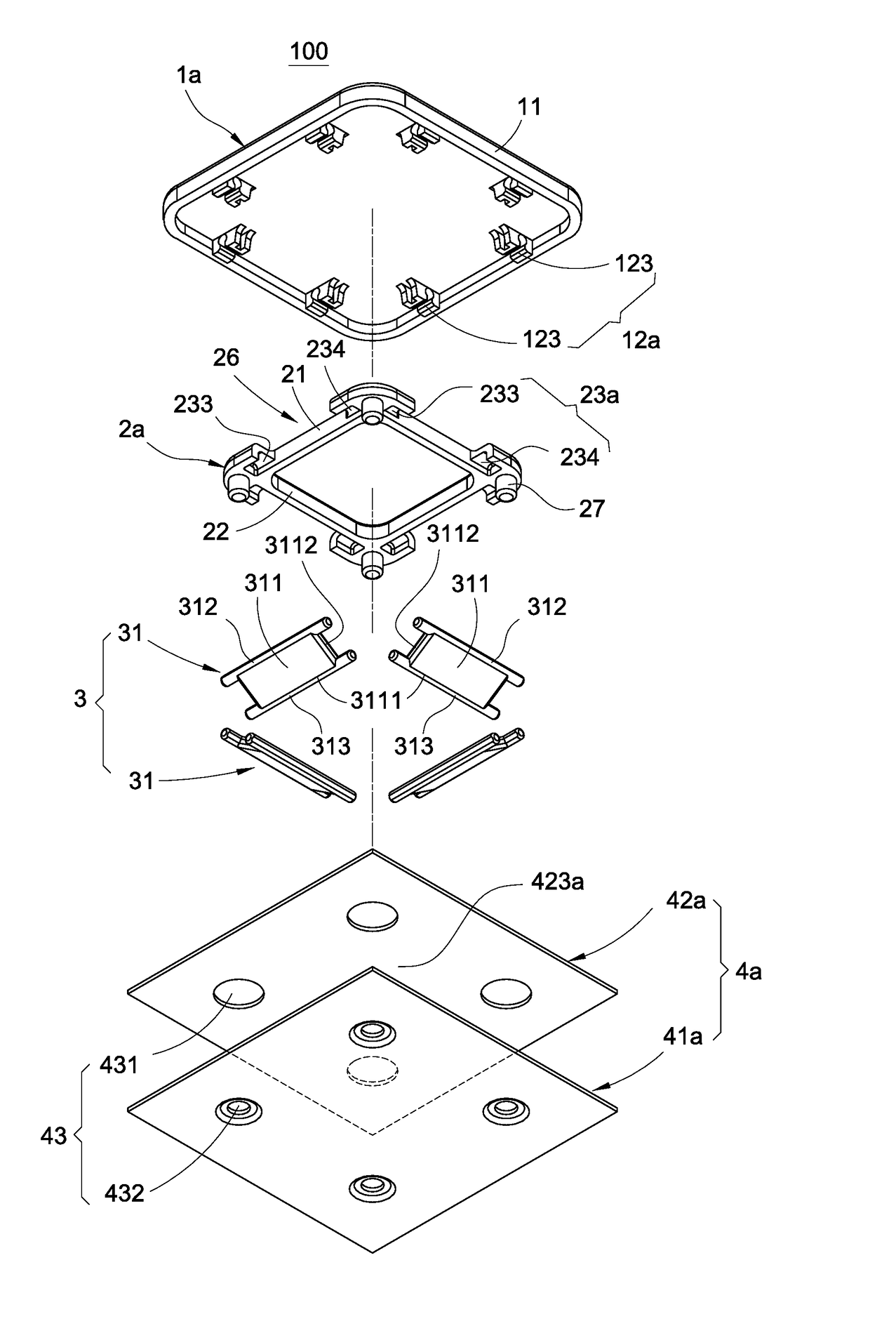
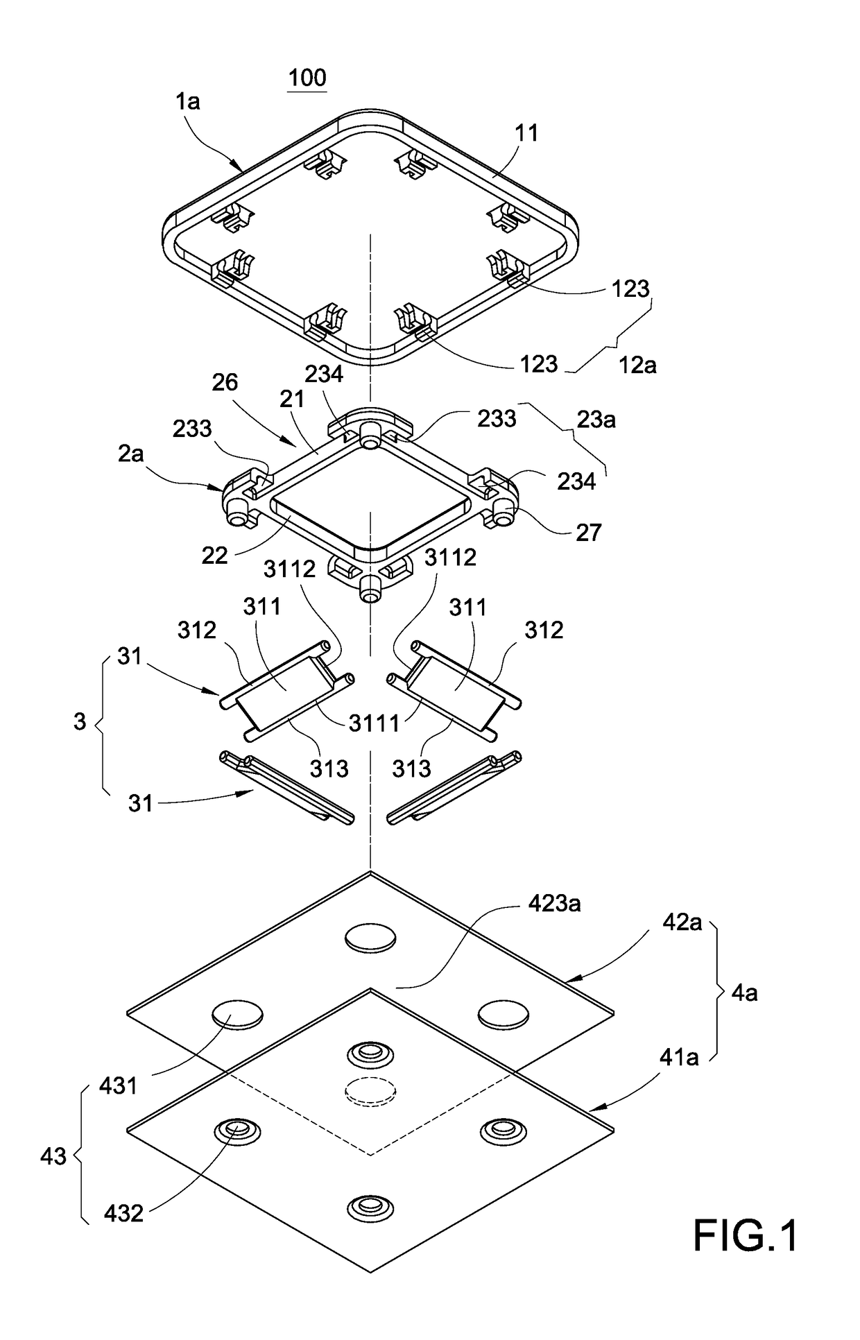
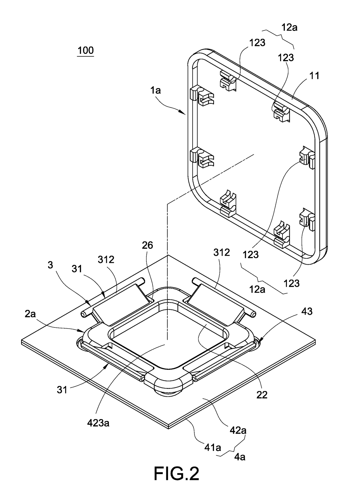
[0025]The key structure 100 of the disclosure, as shown in FIG. 1, FIG. 2 and FIG. 3, comprises a keycap 1a, a frame body 2a, a connecting assembly 3, a carrying body 4a and an elastic member 5. As shown in FIG. 3, the size of the frame 2a is smaller than the size of the keycap 1a so that the keycap 1a correspondingly covers the top of the frame body 2a.

[0026]The carrying body 4a is configured for carrying the keycap 1a, the frame body 2a, the connecting assembly 3 and the elastic member 5. The carrying body 4a comprises a bottom plate 41a and a film circuit board 42a stacked up on the bottom plate 41a. The way of the film circuit board 42a stacked up on the bottom plate 41a is not intended to limit the disclosure. The film circuit board 42a of this embodiment is stacked up on the bottom plate 41a, for example. Furthermore, the carrying body 4a, if required, may be arranged with a plurality of keycaps 1a, a plurality of frame bodies 2a, a plurality of connecting assemblies 3 and a ...

second embodiment

[0045]In the connecting member of the connecting assembly 3b, the connecting member 31 correspondingly connected to the short edge 112 is identical to the connecting member in the first or However, the connecting member 31b correspondingly connected to the long edge 111 is changed into a long connecting member 31b with corresponding length. The carrying body 4b still comprises a bottom plate and a film circuit board stacked up on the bottom plate.

[0046]FIG. 8 shows a key structure 800 of the fourth embodiment of the disclosure. The fourth embodiment is similar to the third embodiment, but the connecting member connected to the long cap edge 111 in the fourth embodiment is different, which is illustrated below.

[0047]In the connecting members, it is still using single connecting member 31 to be correspondingly connected to the short cap edge 112. For the long cap edge 111, however, at least two connecting members arranged in parallel are correspondingly connected to the long cap edge...


PUM


Abstract

A key structure includes a carrying body, a frame body, a keycap and at least two connecting members. The frame body is disposed on the carrying body, and the frame body is disposed with a plurality of sliding grooves. The keycap has a plurality of cap edges and correspondingly covers the top of the frame body, and the keycap is disposed with a plurality of pivoting portions. The at least two connecting members are independent from each other. The at least two connecting members are connected between the keycap and the frame body, corresponding to the two cap edges opposite to each other. Each connecting member includes a pivoting rod and a sliding rod. Each pivoting rod pivots on each pivoting portion. Each sliding rod is slidably limited in each sliding groove, and the pivoting portions are correspondingly located on the outside of the sliding grooves.

Description

TECHNICAL FIELD[0001]The disclosure relates to a key, more particularly to a key structure with preferred structural strength, smooth pressing movement and reliable pressing contact, and a keyboard having the key structure.BACKGROUND OF THE INVENTION[0002]Currently the keys on a keyboard generally comprise a substrate, a keycap and a connecting component movably connected between the substrate and the keycap. The connecting component has a space for an elastic member to go through and move while the elastic member elastically supports between the keycap and the substrate. The substrate is disposed with a circuit layer. The circuit layer is disposed with a trigger switch corresponding to the elastic member. When the keycap is pressed by a hand, the connecting component guides the keycap to move downward and makes the elastic member touch the trigger switch, thereby reaching the goal of signal transmission by tapping the keys of the keyboard.[0003]FIG. 11 is a prior art of a Taiwan pa...

Claims


Application Information

Patent Timeline
Patent Type & Authority Patents(United States)
IPC IPC(8): H01H13/70H01H13/14H01H13/7065
CPCH01H13/14H01H13/7065H01H2205/002H01H2221/044H01H3/122H01H2215/006H01H2221/058
Inventor LIN, CHUN-TINGCHUANG, CHIEH-FANYEH, LIANG-CHUNLEE, CHUN-TE
Owner CHICONY ELECTRONICS
Features
  • R&D
  • Intellectual Property
  • Life Sciences
  • Materials
  • Tech Scout
  • Unparalleled Data Quality
  • Higher Quality Content
  • 60% Fewer Hallucinations
Learn More