Process for drilling a tunnel in which to place a sensor in a cooking vessel and vessel created by said process

a tunnel and sensor technology, applied in the field of tunnel drilling, can solve the problems that the drilling bit, by construction, is never perfectly rectilinear, and achieve the effect of improving the life of the drill bi

Active Publication Date: 2017-08-22
SEB SA
View PDF18 Cites 67 Cited by
  • Summary
  • Abstract
  • Description
  • Claims
  • Application Information

AI Technical Summary

Benefits of technology

[0011]A first portion corresponding to a first hole is thus made in the pre-drilling step. This first hole will serve as a centering tube and will stabilize the end of the longer drill bit used in the deep drilling step for making the second portion, the radial clearance of the longer drill bit end being limited by the wall of the first hole. Indeed, a drill bit, by construction, is never perfectly rectilinear. It always has a runout. Thus, properly guiding the longer drill bit end makes it possible to create a second portion in the form of a second hole along the axis of the first, and thereby obtain a rectilinear tunnel, without deviation, with controlled dimensions that are consistent from one cooking vessel to another.
[0032]Thus, the sensor placement tunnel has a first and second portion, in succession. The first portion, which is larger in diameter, guides the sensor when it is inserted into the placement tunnel, and the second portion, of a smaller diameter, is adjusted to the size of the sensor for precise positioning, and even to slightly hold the sensor at the bottom of the placement tunnel. Consequently, the sensor cannot move around and will measure the temperature of the bottom in a manner that is repeatable and reliable over time.

Problems solved by technology

Indeed, a drill bit, by construction, is never perfectly rectilinear.

Method used


Image

  • Process for drilling a tunnel in which to place a sensor in a cooking vessel and vessel created by said process
  • Process for drilling a tunnel in which to place a sensor in a cooking vessel and vessel created by said process
  • Process for drilling a tunnel in which to place a sensor in a cooking vessel and vessel created by said process

Examples


Embodiment Construction

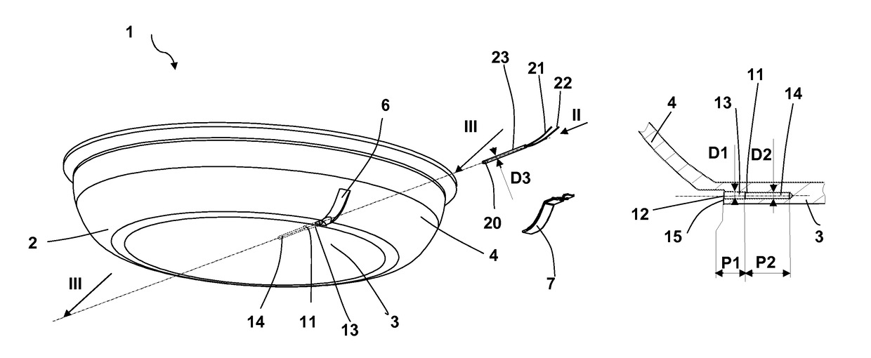
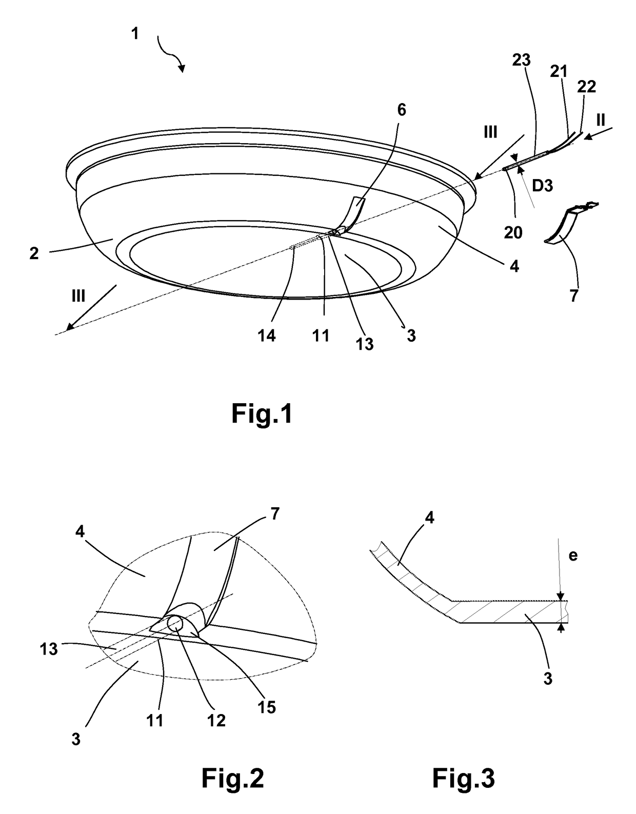
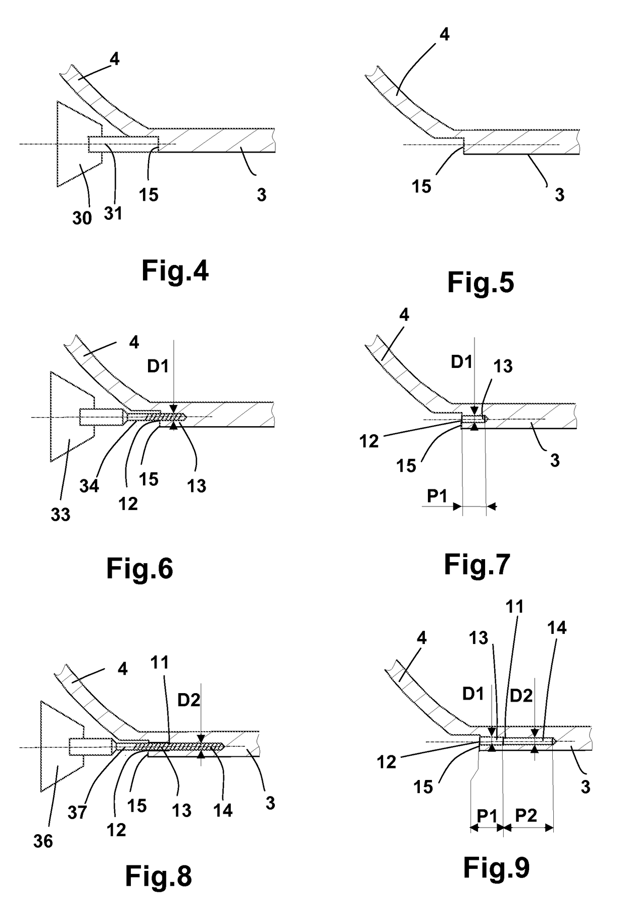
[0044]As can be seen in FIGS. 1 and 2, a bowl (2) of a cooking vessel (1) has of a bottom (3) and a side wall (4). The bowl (2) is made of aluminum, for example, by stamping a disc or by a casting operation. The bottom (3) has a thickness (e) equal to 4 millimeters, in which a tunnel (11) is arranged for the placement of a sensor (20). The placement tunnel (11) forms an opening (12) in the side wall (4) and extends from said opening (12), radially toward the center of the bottom (3). The placement tunnel (11) comprises, from the opening (12), a first portion (13) formed by a cylindrical hole of Diameter D1 (FIG. 9), and then a second portion (14) formed by a cylindrical hole of Diameter D2 (FIG. 9), Diameter D1 being greater than Diameter D2. The first and second portions (13, 14) have the same longitudinal axis.

[0045]The sensor (20), which can be seen in FIG. 1, is a temperature sensor, in particular, formed by an NTC or a thermocouple. The term NTC refers to a Negative Temperature...


PUM

PropertyMeasurementUnit
depthaaaaaaaaaa
depthaaaaaaaaaa
depthaaaaaaaaaa

Abstract

Provided is a process for drilling a tunnel (11) in which to place a sensor, in particular a temperature sensor, in a cooking vessel (1) comprising a bowl (2) with a bottom (3) having a thickness (e), said process comprising a step for drilling said tunnel made in the thickness (e). The drilling step comprises a pre-drilling step using a drill bit with a diameter of D1, and a deep drilling step using a drill bit with a diameter of D2, D1 being greater than D2.

Description

CROSS-REFERENCE TO RELATED APPLICATION[0001]This application claims priority to French Patent Application No. 1460585 filed Nov. 3, 2014, the disclosure of which is hereby incorporated in its entirety by reference.FIELD OF THE INVENTION[0002]This invention pertains to a process for drilling a tunnel in which to place a sensor in a cooking vessel, and more specifically a tunnel in which to place a temperature sensor, and a cooking vessel created by such a process. The cooking vessel is intended to be positioned on a hot plate, burner or the like, for cooking food, such as a frying pan, saucepan, sauté pan, stockpot or pressure cooker for example.DESCRIPTION OF RELATED ART[0003]There exists, in patent EP1591049, a cooking vessel with a bottom and a temperature sensor positioned inside a placement tunnel made in the bottom. The process for making the sensor placement tunnel, as described in said document, comprises a drilling step.[0004]However, standard cooking vessels have bottoms wi...

Claims


Application Information

Patent Timeline
Patent Type & Authority Patents(United States)
IPC IPC(8): B23B35/00A47J37/10A47J27/00A47J27/08
CPCB23B35/00A47J27/002A47J27/08A47J37/10A47J2202/00B23B2222/04Y10T408/03Y10T408/23Y10T409/303752A47J36/06A47J36/36B23B2270/48A47J27/00
Inventor LINGLIN, BENO TPERREAL, SYLVAINCHARVIN, STEPHANE
Owner SEB SA
Why Eureka
Try Eureka