
Package, light emitting device, and methods of manufacturing the package and the light emitting device

a technology of light emitting devices and packaging, which is applied in the direction of basic electric elements, semiconductor devices, electrical equipment, etc., to achieve the effect of suppressing burr production, easy manufacturing, and suppressing burr production

Active Publication Date: 2017-08-22
NICHIA CORP
View PDF16 Cites 0 Cited by
  • Summary
  • Abstract
  • Description
  • Claims
  • Application Information

AI Technical Summary

Benefits of technology

[0010]The present disclosure provides a package and a light emitting device with which production of burrs can be suppressed, and methods of manufacturing the package and the light emitting device easily.
[0015]With the package and the light emitting device of the present disclosure, production of burrs can be suppressed.
[0016]Further, according to the methods of manufacturing a package and a light emitting device of the present disclosure, a package and a light emitting device with which production of burrs is suppressed can be easily manufactured.

Problems solved by technology

Since such resin burrs invite a bonding failure of LED elements or wires, the burrs must be removed.

Method used


Image

  • Package, light emitting device, and methods of manufacturing the package and the light emitting device
  • Package, light emitting device, and methods of manufacturing the package and the light emitting device
  • Package, light emitting device, and methods of manufacturing the package and the light emitting device

Examples


example

Example 1

[0085]In the following, Example of the present disclosure will be described. Molding was performed using the package-manufacturing purpose mold K including the projection portion 75 provided with protrusion portions 78 and 79 as shown in FIG. 4 and using a transfer molding machine.

[0086]The molding was performed using the package-manufacturing purpose mold K, under the conventional contacting pressure and injection pressure conditions with which resin burrs were produced when molding was performed using a conventional mold including a projection portion 75 having the shape without the protrusion portions 78 and 79. Then, whether or not burrs were produced was checked.

[0087]As a result, it was found that burrs were not produced at the metal exposed portion of each of the first lead electrode 20 and the second lead electrode 30 with use of the package-manufacturing purpose mold K.

[0088]Further, it was found that the second bottom surface portion 75b formed at the projection p...


PUM


Abstract

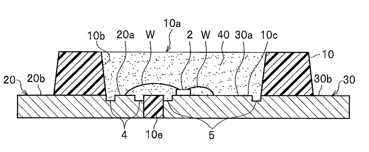
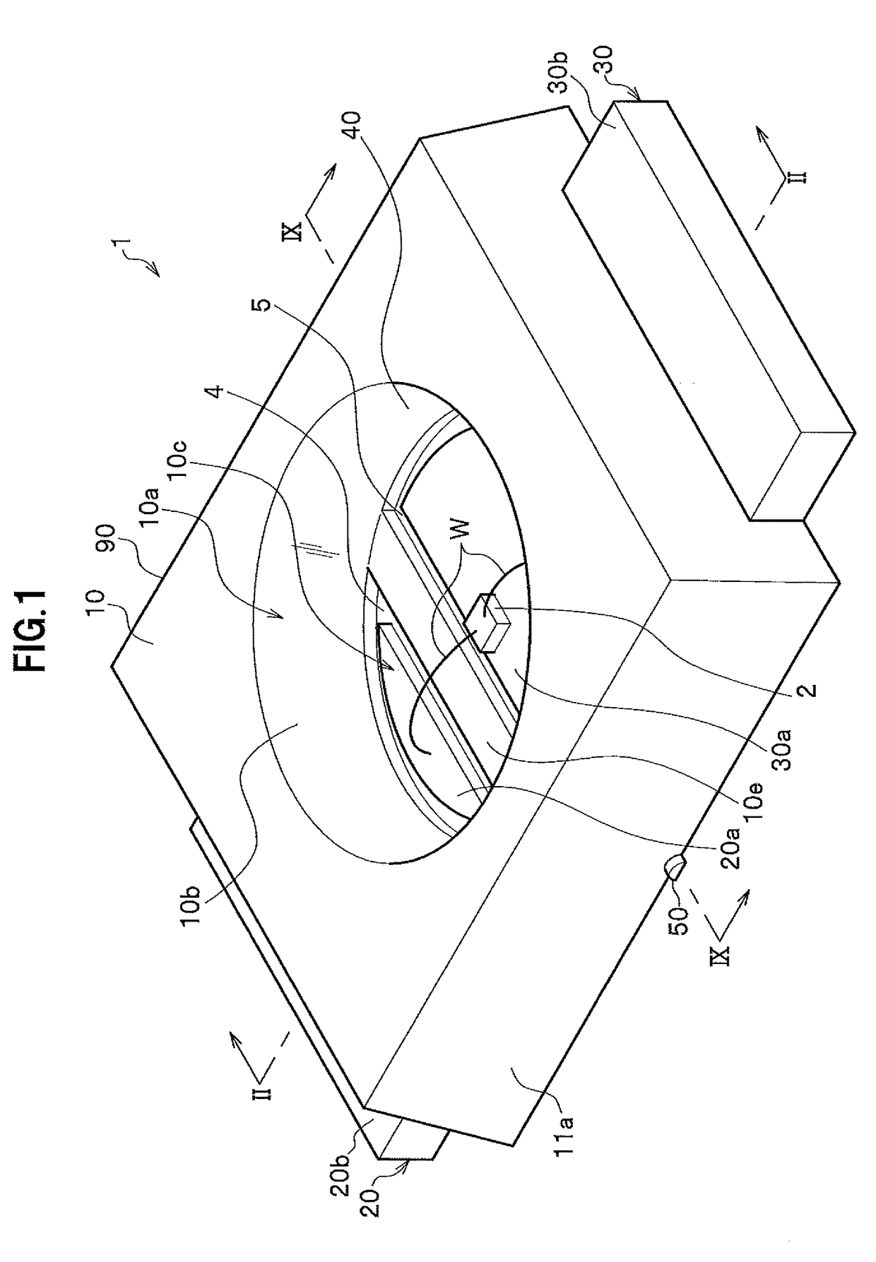
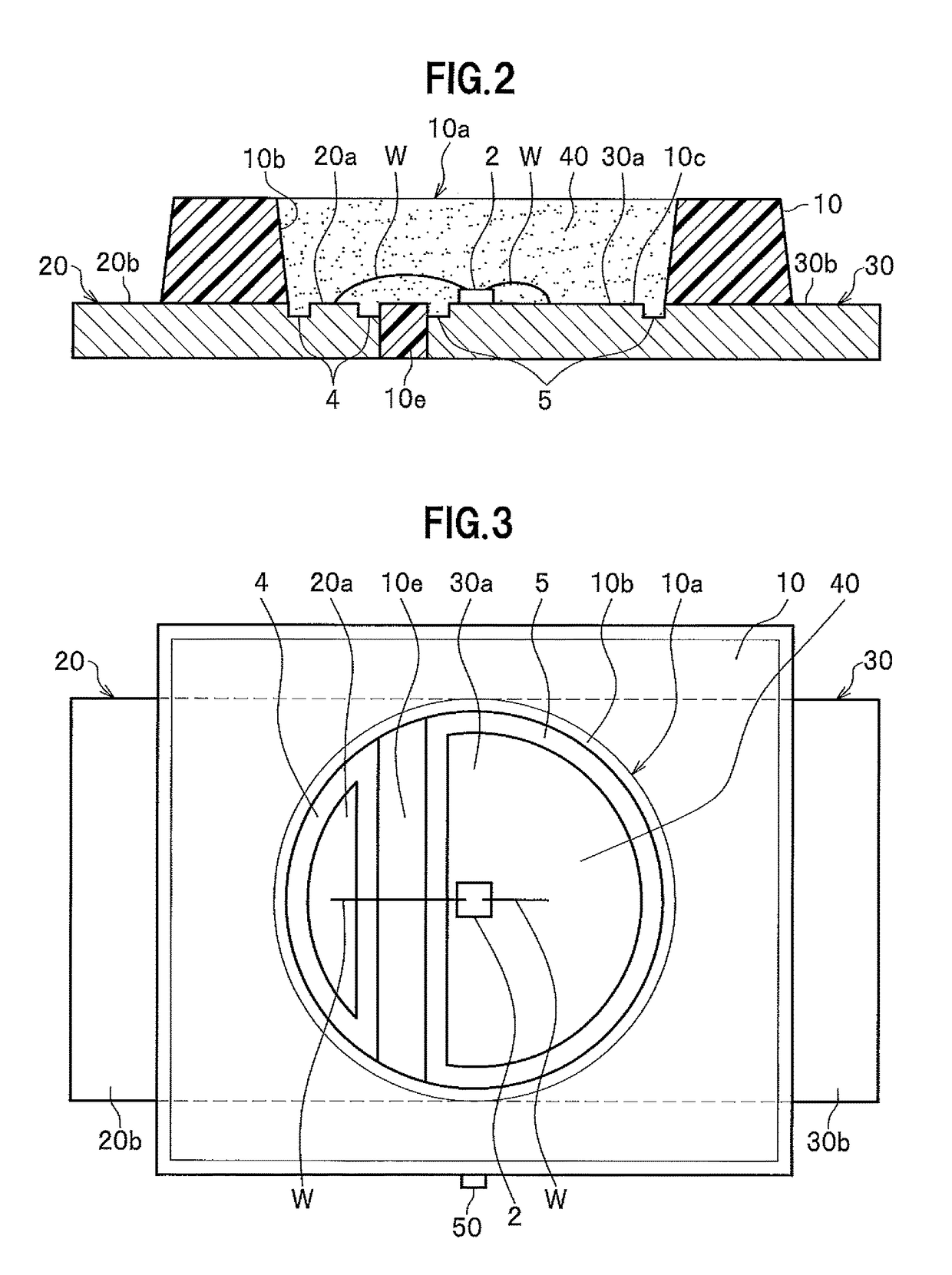
A package and a light emitting device with which production of burrs can be suppressed, and methods of manufacturing the package and the light emitting device easily are provided. A package includes a pair of lead electrodes made of metal plates and a resin molded body. A recess portion for mounting a light emitting element is formed. The pair of lead electrodes are exposed on a bottom surface of the recess portion. At least one of the pair of lead electrodes includes a groove portion that is formed on the metal plate and along a periphery of a surface of the metal plate exposed on a bottom surface of the recess portion.

Description

CROSS-REFERENCE TO RELATED PATENT APPLICATION[0001]The present application claims priority to Japan Patent Application No. 2014-244525, filed Dec. 2, 2014, which is incorporated herein by reference in its entirety.BACKGROUND[0002]1. Technical Field[0003]The present disclosure relates to a package, a light emitting device, and methods of manufacturing the package and the light emitting device.[0004]2. Description of Related Art[0005]A process of manufacturing a light emitting diode (hereinafter referred to as an LED) includes a package molding step. Particularly, what is generally employed is transfer molding, which is a molding method according to which a lead frame is set in a mold and liquid resin is injected. However, with such a manufacturing method, the resin flows into a clearance between the lead frame and the mold, whereby resin burrs are produced. Since such resin burrs invite a bonding failure of LED elements or wires, the burrs must be removed. Accordingly, conventionally...

Claims


Application Information

Patent Timeline
Patent Type & Authority Patents(United States)
IPC IPC(8): H01L33/54H01L33/62H01L33/48
CPCH01L33/54H01L33/486H01L33/62H01L2224/48091H01L2224/48247H01L2224/48257H01L2933/0033H01L2933/0066H01L2924/00014
Inventor ABE, KOJI
Owner NICHIA CORP
Learn More