Image pickup apparatus

Active Publication Date: 2007-10-04
EVIDENT CORP
View PDF19 Cites 2 Cited by
  • Summary
  • Abstract
  • Description
  • Claims
  • Application Information

AI Technical Summary

Benefits of technology

[0017]In the image pickup apparatus of the present invention, it is desirable that the dustproof glass has an antireflection coating, applied to at least one surface, reducing a reflectance in an infrared wavelength region or an ultraviolet wavelength region, or the infrared wavelength region and the ultraviolet wavelength region, in addition to the reflectance in a visible region.
[0019]According to the present invention, it is possible to obtain the image pickup apparatus in which the optical property can be arbitrarily selected by mounting and demounting or replacing the optical filter according to the purpose of use, the production of flare is suppressed according to the observation of a specimen of different transmittance or reflectance, with a low-cost and simple structure, and even when the optical filter is mounted or demounted, the observation image can be obtained in a favorable focusing condition. As a result, even when a specimen with high reflectance is photographed, the production of flare can be suppressed and it becomes possible to accommodate the photographing of the specimen of luminance in a wider range. Moreover, a low-cost electronic imaging apparatus that is capable of eliminating flare at a low cost can be realized.

Problems solved by technology

Consequently, there is the problem that in the imaging apparatus using an electronic image sensor with a high sensitivity, feeble flare is also imaged with a good sensitivity, and particularly, when a living specimen of high transmittance and a metallic specimen of high reflectance are photographed, flare is liable to become prominent.
In particular, in the microscope observation that is small in focal depth as in a total reflection fluorescence observation of a living body, the shift of the image-forming position (the focal position) of the observation image produces a considerable adverse effect on the focusing condition of an image obtained through the image sensor.

Method used


Image

  • Image pickup apparatus
  • Image pickup apparatus
  • Image pickup apparatus

Examples


embodiment 1

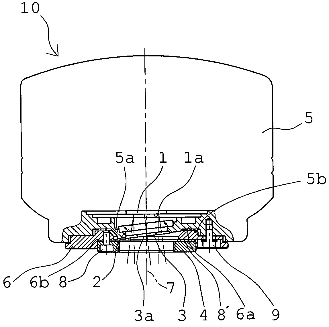
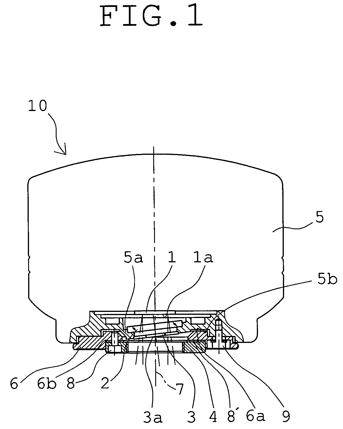
[0039]FIG. 1 shows essential parts of the structure of an electronic imaging apparatus for microscopes as the image pickup apparatus of Embodiment 1 in the present invention. An electronic imaging apparatus 10 of Embodiment 1 has a CCD 1 as the image sensor recording image information, a dustproof glass 2, an optical filter 3, and a C-mount 4 as a camera mount. The CCD 1 is provided inside a body section 5. The dustproof glass 2 is constructed with a plane-parallel glass, is located in front of the CCD 1 (on the lower side in the plane of the page), and is fixedly placed in an inclined state on a glass mounting portion 5a of the body section 5 to keep hermeticity of the periphery of the CCD 1. The optical filter is removably placed as described later in front of the dustproof glass 2. The C-mount 4 is located before the optical filter 3.

[0040]To the body section 5, a mount section 6 for mounting the C-mount 4 is connected. The mount section 6 is such that one surface 6a comes in con...

embodiment 2

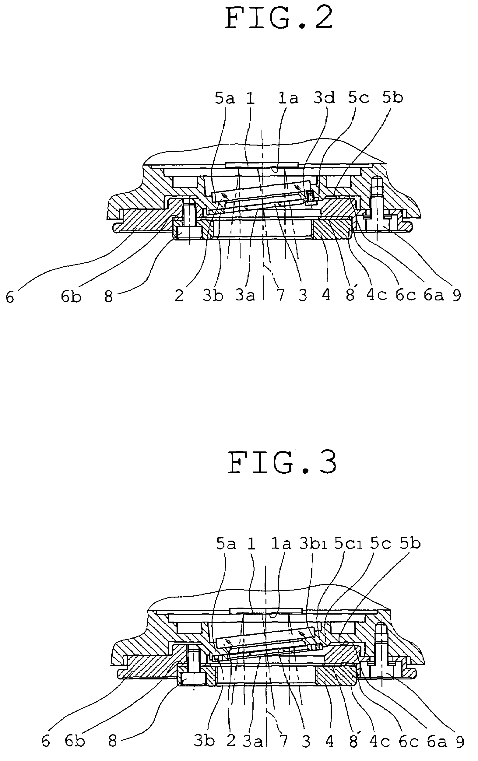
[0055]FIG. 8 shows essential parts of the electronic imaging apparatus for microscopes as the image pickup apparatus of Embodiment 2 in the present invention. An electronic imaging apparatus 10′ of Embodiment 2 is constructed so that a lens 3″ provided with the function of the optical filter is removably placed instead of the optical filter 3 in the electronic imaging apparatus 10 of Embodiment 1.

[0056]According to the electronic imaging apparatus 10′ of Embodiment 2 constructed as mentioned above, the image pickup apparatus of the structure that formerly has required a thick optical filter for a nearly plane-parallel plate can be constructed with a lens of relatively small thickness. It is also possible to correct residual aberration contained in a light beam incident on the image pickup apparatus and to provide the function of moderating a shading phenomenon by correcting the angle of a light ray so as to accommodate the characteristic of the angle of incidence of the light ray on...


PUM


Abstract

An image pickup apparatus has an image sensor recording image information; a dustproof glass for keeping hermeticity of the periphery of the image sensor, placed in front of the image sensor; an optical filter removably placed in front of the dustproof glass; and a camera mount placed in front of the optical filter. The image pickup apparatus further has a parfocal adjusting device in which a focal position where the optical filter is demounted can be adjusted so as to be nearly equal to the focal position where the optical filter is mounted.

Description

[0001]This application claims benefits of Japanese Application No. 2006-99400 filed in Japan on Mar. 31, 2006, the contents of which are hereby incorporated by reference.BACKGROUND OF THE INVENTION[0002]1. Field of the Invention[0003]This invention relates to an image pickup apparatus, such as an electronic imaging apparatus, mounted to and used in a microscope in order to photograph a specimen, for instance, and in particular, to an image pickup apparatus in which different optical filters can be selected and used in accordance with applications.[0004]2. Description of Related Art[0005]Conventional image pickup apparatuses of this type are set forth, for example, in Japanese Patent Kokai Nos. 2001-125152, 2001-296583, 2003-298855, and 2004-312552. Each of these image pickup apparatuses is designed so that an optical filter to be used can be arbitrarily selected according to the purpose of image pickup.[0006]In recent years, as image pickup apparatuses for microscopes, imaging appar...

Claims


Application Information

Patent Timeline
IPC IPC(8): H04N5/225
CPCG02B21/361G03B17/00G02B21/362
Inventor MOCHIZUKI, TSUYOSHIHIRANO, RYUICHIYONETANI, ATSUSHI
Owner EVIDENT CORP
Why Eureka
Try Eureka