Hot bulge forming die apparatus

a technology of forming die and hot bulge, which is applied in the direction of metal-working apparatus, manufacturing tools, shaping tools, etc., can solve the problems of increasing production costs, increasing workpiece dimensions, and not constant dimensions of formed products

Inactive Publication Date: 2011-01-27
HONDA MOTOR CO LTD
View PDF14 Cites 2 Cited by
  • Summary
  • Abstract
  • Description
  • Claims
  • Application Information

AI Technical Summary

Benefits of technology

[0018]One or more embodiments of the invention provide a hot bulge f

Problems solved by technology

Incidentally, when forming workpieces one after another by the hot bulge forming dies, there has been caused a problem that dimensions of workpieces gradually increase until the number of times of forming reaches a certain number of times of forming.
However, the dimensions of the formed products gradually increase until the shapes of the dies become s

Method used


Image

  • Hot bulge forming die apparatus
  • Hot bulge forming die apparatus
  • Hot bulge forming die apparatus

Examples


Embodiment Construction

[0038]An exemplary embodiment of the invention will be described by reference to the drawings.

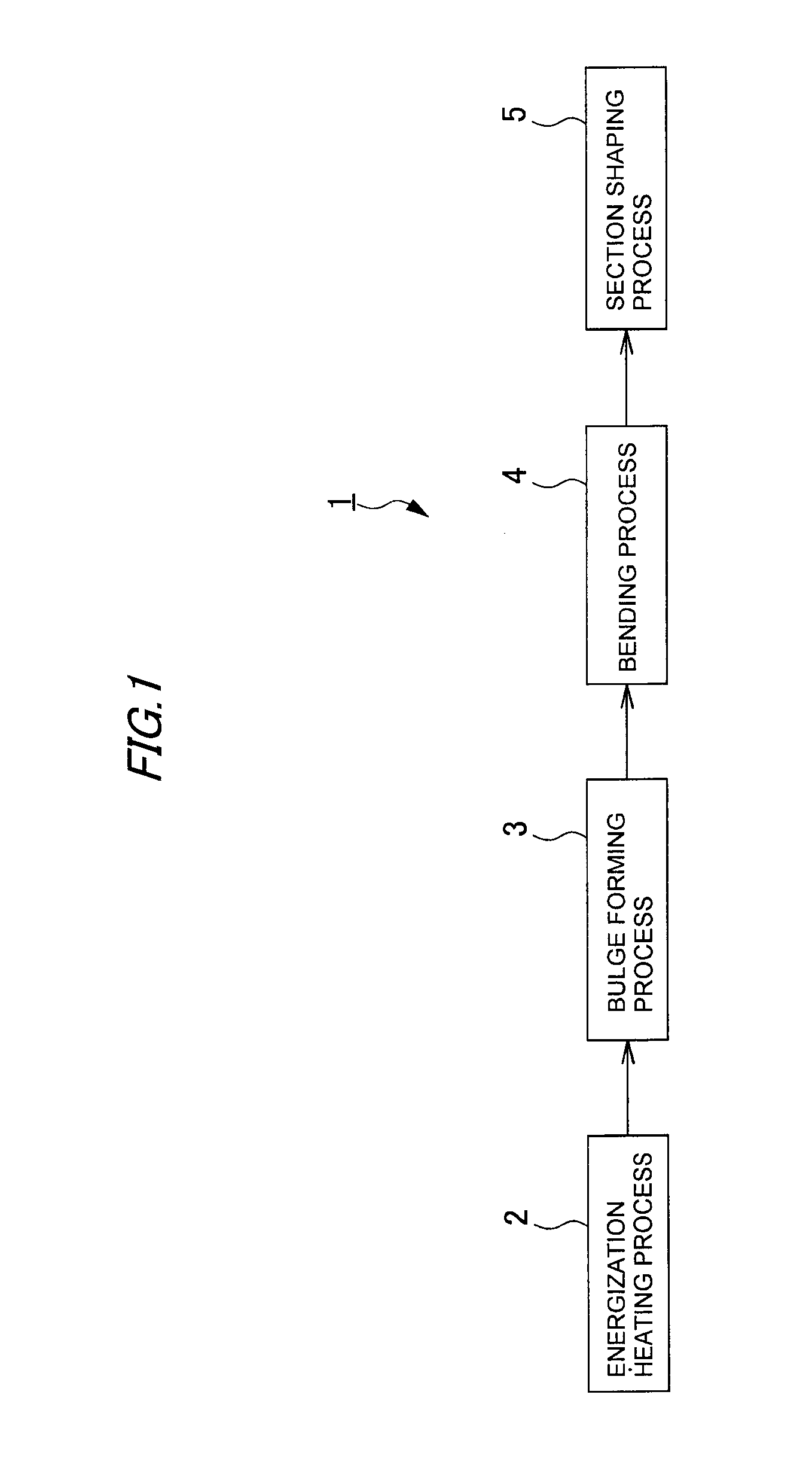
[0039]FIG. 1 is a schematic block diagram showing operations of a hot bulge forming apparatus 1 to which hot bulge forming die apparatus of the invention are applied.

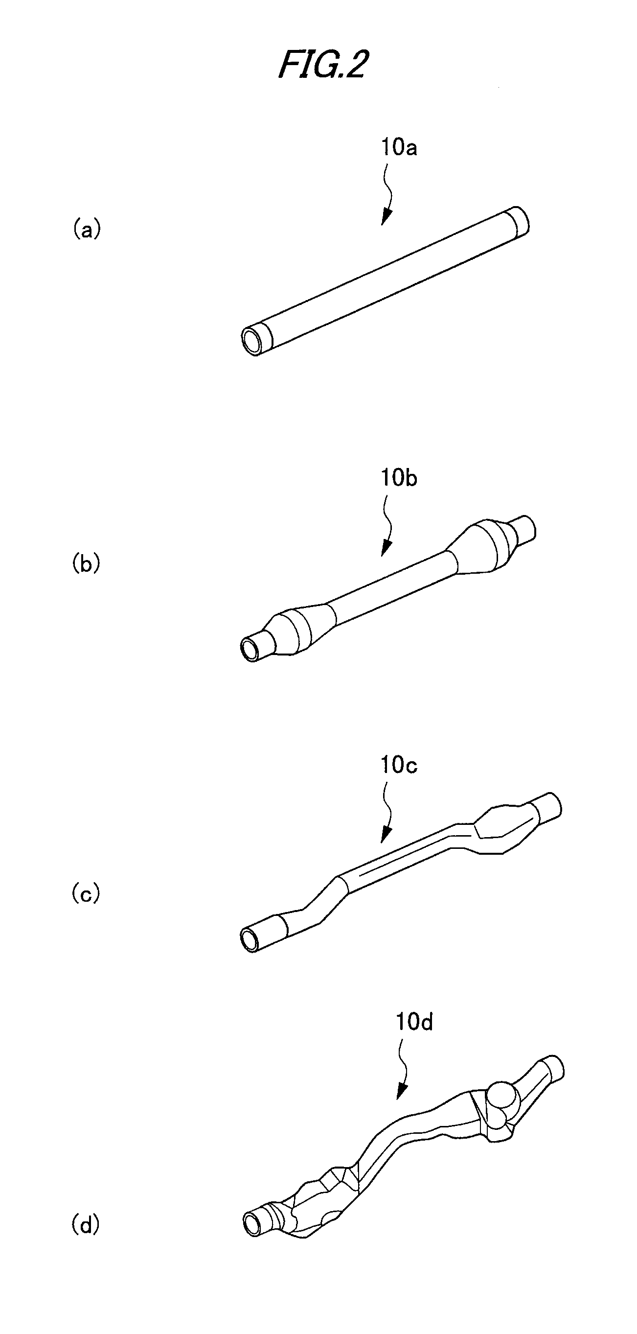
[0040]FIG. 2 ((a) portion to (d) portion) shows perspective views of tubular materials 10a to 10d which represent workpieces which are formed at respective steps by the hot bulge forming apparatus 1.

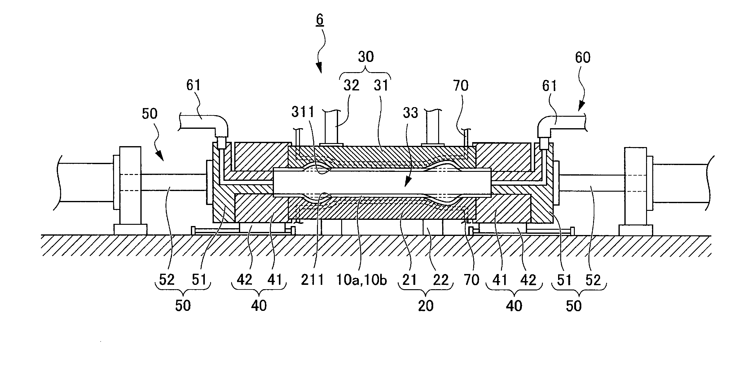
[0041]The hot bulge forming apparatus 1 is designed to execute an energization heating process 2, a bulge forming process 3 and a bending process 4 which constitutes a pre-forming process, and a section shaping process 5 which constitutes a final forming process sequentially in that order.

[0042]Specifically, in the energization heating process 2, a tubular material 10a, which is made of an aluminum alloy and which extends substantially rectilinearly, is heated.

[0043]In the bulge forming process 3, portions of the tubular material 10...


PUM

PropertyMeasurementUnit
Stiffnessaaaaaaaaaa
Thermal expansion coefficientaaaaaaaaaa

Abstract

A hot bulge forming die apparatus forms a preheated tubular material 10a into a tubular material 10d. The hot bulge forming die apparatus includes a lower die 21B having a cavity surface 211B and an upper die 31B having a cavity surface 311B. An elongated hole 215 is formed in a circumferential edge portion 215 of the lower die 21B so as to extend outwards, and a projection 315 is formed on a circumferential edge portion 314 of the upper die 31B so as to fit in the elongated hole 215. When the dies are clamped together, the projection 315 formed on the circumferential edge portion 314 of the upper die 31B fits in the elongated hole 215 formed in the circumferential edge portion 214 of the lower die 21B.

Description

BACKGROUND OF THE INVENTION[0001]1. Field of the Invention[0002]The present invention relates to a hot bulge forming apparatus and more particularly to a hot bulge forming die apparatus for forming a pre-heated tubular workpiece.[0003]2. Related Art[0004]Conventionally, there has been known a hot bulge forming process in which high-pressure air is supplied into a tubular workpiece disposed between dies so as to form the tubular workpiece into a shape of a cavity defined between the dies.[0005]Specifically, in this hot bulge forming process, for example, a tubular workpiece is preheated, and the tubular workpiece so heated is disposed between a pair of dies. Next, the dies are clamped together while the workpiece is restrained at both lengthwise ends thereof, and high-pressure air is supplied into the tubular workpiece so that the workpiece is pressed against cavity surfaces of the dies. Thereafter, this state is maintained for a certain length of time to cool the workpiece by the di...

Claims


Application Information

Patent Timeline
IPC IPC(8): B21D37/12
CPCB21D26/047Y10T29/49805B21D37/16B21D37/12
Inventor ISHIHARA, YOSHIMITSUYAMAMOTO, DAISUKEKANOU, TAKAYUKI
Owner HONDA MOTOR CO LTD
Why Eureka
Try Eureka