Occupant restraint system

a technology for occupants and seats, applied in the direction of pedestrian/occupant safety arrangements, vehicle components, superstructure subunits, etc., can solve the problems of increased production costs and increased number of components, and achieve the effect of preventing the dislocation of the pillar garnish and simple construction

Inactive Publication Date: 2006-11-14
HONDA MOTOR CO LTD
View PDF7 Cites 33 Cited by
  • Summary
  • Abstract
  • Description
  • Claims
  • Application Information

AI Technical Summary

Benefits of technology

[0006]The invention was made in view of these situations, and an object thereof is to provide an occupant restraint system which can prevent the dislocation of the pillar garnish when the air bag is deployed with a simple construction which does not call for an increase in the number of components.
[0011]According to the construction, even in case the deploying air bag is caught at an upper end of the pillar garnish, which covers the pillar when the air bag which is arranged in such a manner as to extend along the side portion of the roof in the folded state is inflated so as to be deployed along the side of the pillar which faces the passenger compartment, by causing the distal end of the projection integrally formed on the inner surface of the pillar garnish to be inserted in the hole formed in the pillar, the dislocation of the pillar garnish from the pillar is prevented to thereby enable the smooth deployment of the air bag. In addition, since the rod-like projection is formed into a simple shape when compared with a clip or a hook, the projection is easy to be molded, whereby an increase in the production costs of the pillar garnish can be suppressed to a minimum level. Moreover, since no special separate member is required, there is caused no risk that the number of components is increased.

Problems solved by technology

Incidentally, with the related-art occupant restraint system, the complex construction of the bridge on the pillar garnish has not only made the mold for the pillar garnish expensive to thereby cause a problem that the production costs are increased, but has also required special components such as the straps and bolts to thereby cause a problem that the number of components is increased.

Method used


Image

  • Occupant restraint system
  • Occupant restraint system
  • Occupant restraint system

Examples


Embodiment Construction

[0020]A mode for carrying out the invention will be described below based on an embodiment of the invention which is illustrated in the accompanying drawings.

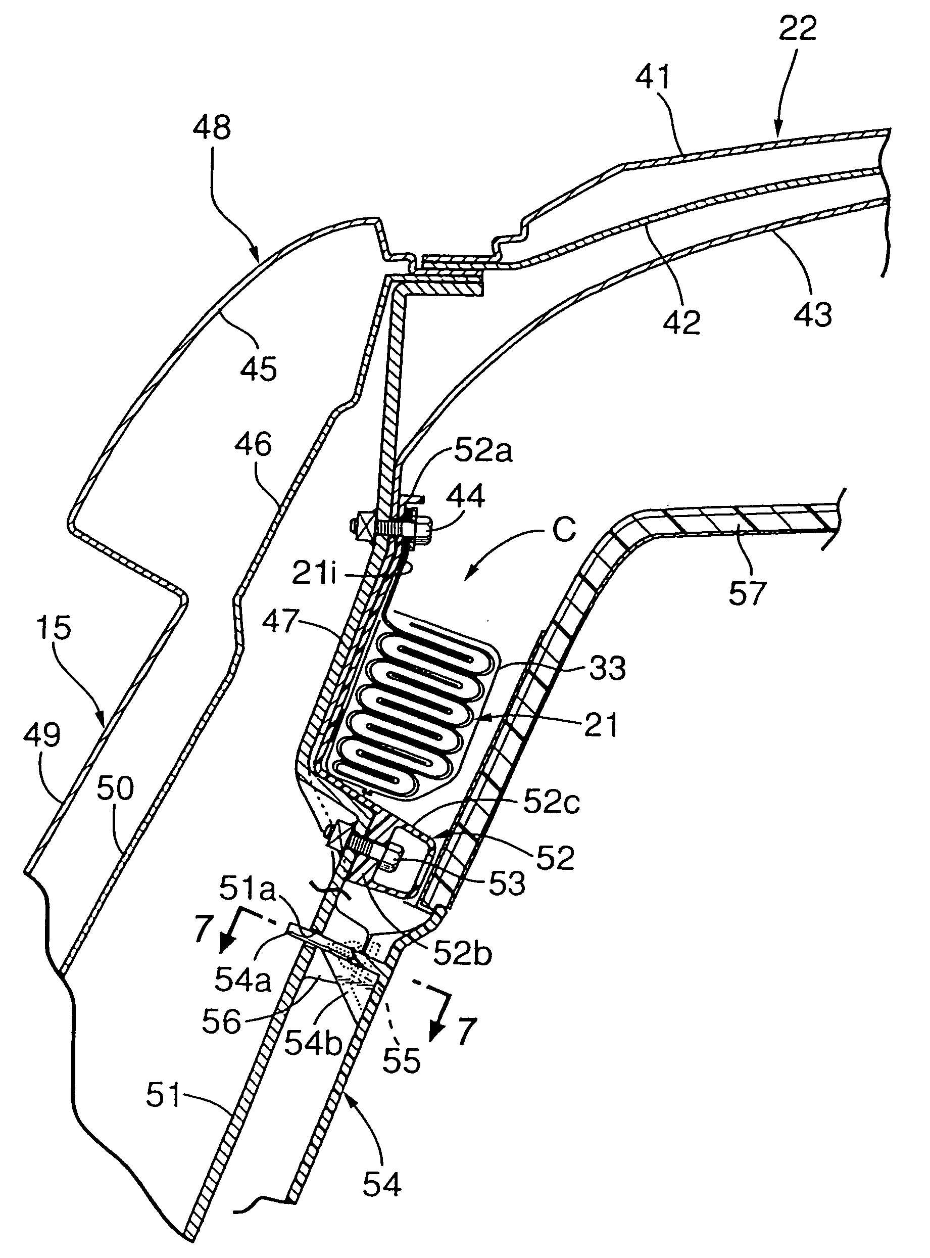
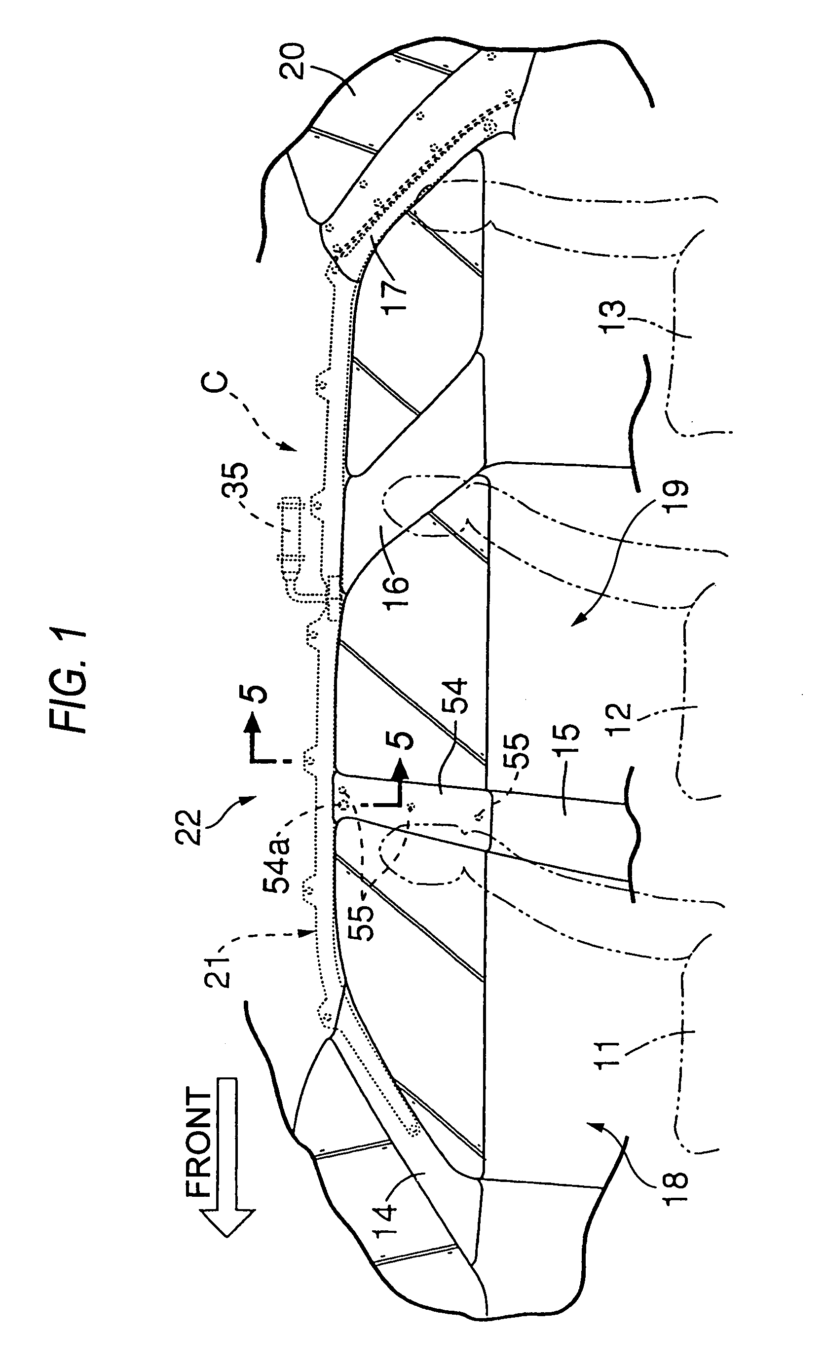
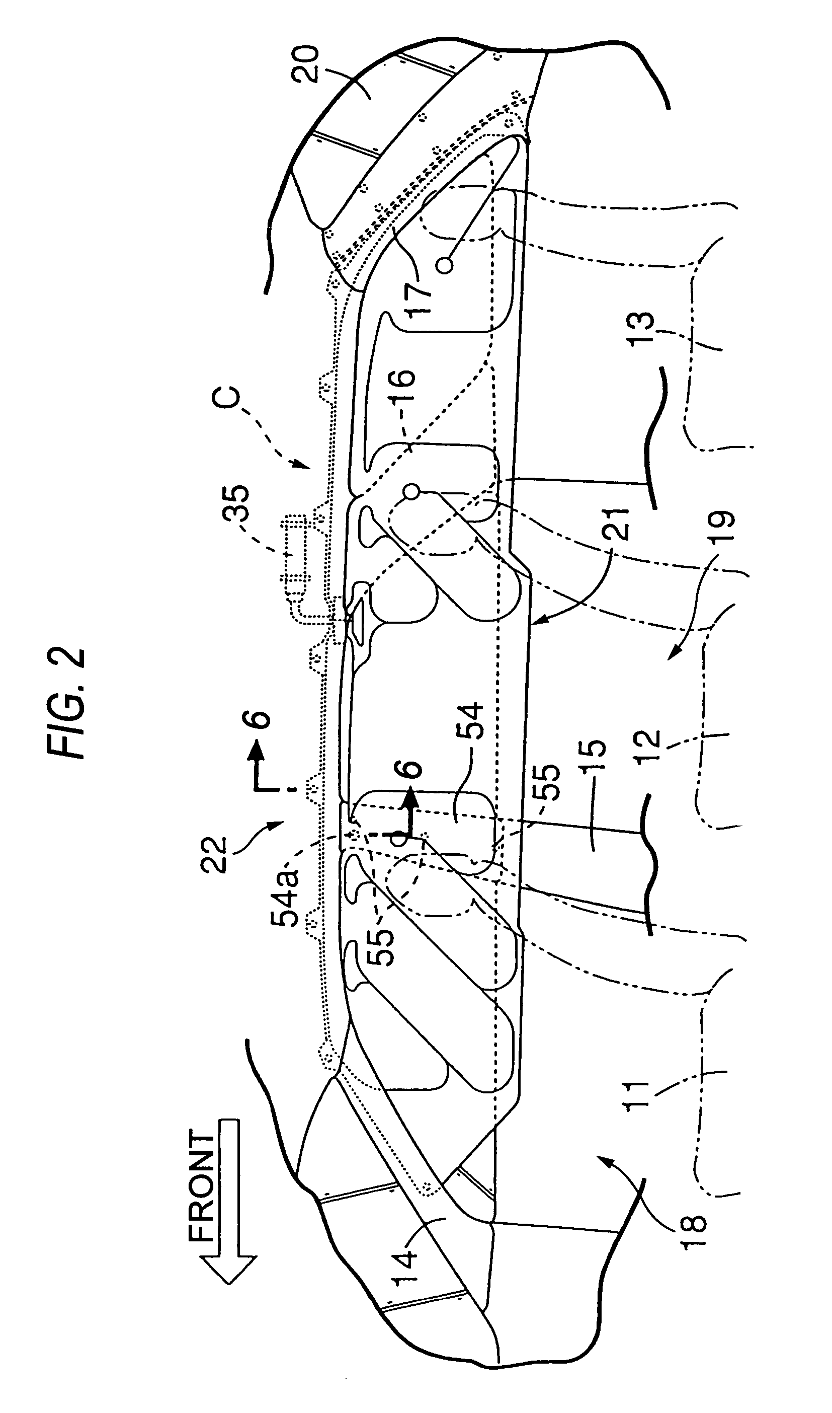
[0021]FIGS. 1 to 7 show an embodiment of the invention, in which FIG. 1 is a drawing showing an inside of a passenger compartment of a vehicle when an air bag is in a non-deployed state, FIG. 2 is a drawing showing the inside of the passenger compartment of the vehicle when the air bag has been deployed, FIG. 3 is an enlarged view of a main part of FIG. 2, FIG. 4 is an exploded perspective view of an occupant restraint system, FIG. 5 is an enlarged cross-sectional view taken along the line 5—5 in FIG. 1, FIG. 6 is an enlarged cross-sectional view taken along the line 6—6 in FIG. 2, and FIG. 7 is a cross-sectional view taken along the line 7—7 in FIG. 5.

[0022]As shown in FIG. 1, a recreational vehicle or RV has a front-row seat 11, a center-row seat 12 and a rear-row seat 13. The RV also has A pillars 14, B pillars 15, C pillars...


PUM


Abstract

An occupant restraint system includes an air bag arranged inside a roof side rail in a folded state. When a vehicle is involved in a collision, the air bag so arranged is inflated with a gas generated by an inflator so as to be deployed along an inner surface of a side portion of a passenger compartment in a curtain-like fashion. In a pillar garnish which covers a side of a pillar inner of a B pillar which faces a passenger compartment side, a rod-like projection provided on an inner surface of the pillar garnish at an upper portion thereof in such a manner as to project therefrom is inserted into a hole formed in the pillar inner. Even in case the air bag which is being deployed pushes against an upper end of the pillar garnish, the dislocation of the pillar garnish from the pillar inner is prevented.

Description

BACKGROUND OF THE INVENTION[0001]1. Field of the Invention[0002]The present invention relates to an occupant restraint system in which an air bag in a folded state is arranged in such a manner as to extend along a side portion of a roof, so that, when a vehicle is involved in a collision, the air bag is inflated with a gas generated by an inflator so as to be deployed in a curtain-like fashion along an inner surface of a side portion of a passenger compartment.[0003]2. Description of the Related Art[0004]The occupant restraint system is known by JP-A-2001-39260. In this occupant restraint system, when the folded air bag arranged in such a manner as to extend along the side portion of the roof is deployed downwardly along a center pillar (a B pillar), the air bag may be caught at an upper end of the pillar garnish which covers the side of the center pillar which faces the passenger compartment, and the pillar garnish is dislocated from the center pillar, whereby the smooth deployment...

Claims


Application Information

Patent Timeline
Patent Type & Authority Patents(United States)
IPC IPC(8): B60R21/16B60R21/20B60R13/02B60R21/213B60R21/233
CPCB60R13/0206B60R13/025B60R21/213B60R21/215B60R21/232B60R2013/0287B60R2013/0293B60R2021/161B60R2021/23316B60R2021/2617
Inventor TOTSUKA, HIROFUMIAOKI, TAKASHIUTSUMI, HIDETOSHITAKEMURA, NAOKISAITO, YUICHI
Owner HONDA MOTOR CO LTD
Why Eureka
Try Eureka