Shaping apparatus

a technology of shaping apparatus and flattening roller, which is applied in the direction of adding manufacturing processes, manufacturing tools, and applying layer means, etc., can solve the problems of affecting the shape the deformation of the three-dimensional object in the middle of shaping, and the failure of the three-dimensional object to achieve the effect of suppressing the occurrence of shaping failures of the three-dimensional obj

Inactive Publication Date: 2021-02-25
MIMAKI ENG
View PDF0 Cites 0 Cited by
  • Summary
  • Abstract
  • Description
  • Claims
  • Application Information

AI Technical Summary

Benefits of technology

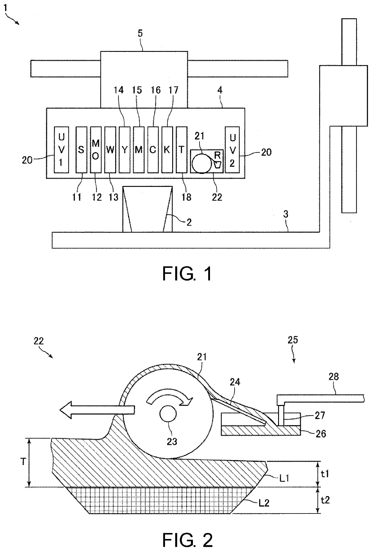
[0012]In the shaping apparatus of the present disclosure, the non-ink adhering portion including a liquid repellent surface, which is a surface having liquid repellency, or a non-ink adhering portion including a recess that is depressed toward an inner side in a radial direction of the flattening roller are provided on the outer peripheral surface of the flattening roller. Thus, in the present disclosure, even if the upper surface of the cured ink and the flattening roller come into contact with each other, a part of the cured ink is less likely to be scraped off by the non-ink adhering portion. Therefore, in the present disclosure, even if the upper surface of the cured ink and the flattening roller come into contact with each other, a part of the cured ink is less likely to be scraped off by the flattening roller. Thus, in the present disclosure, even if the upper surface of the cured ink and the flattening roller come into contact with each other, production of shavings can be suppressed.
[0013]Furthermore, in the present disclosure, the frictional force between the upper surface of the ink and the flattening roller can be reduced since the non-ink adhering portion is provided on the outer peripheral surface of the flattening roller. Therefore, in the present disclosure, even if the upper surface of the cured ink and the flattening roller come into contact with each other, generation of abnormal vibration of the flattening roller, deformation of the three-dimensional object being shaped, and the separation from the shaping table of the three-dimensional object being shaped can be suppressed. As a result, in the present disclosure, even when the three-dimensional object is shaped by the multi-pass method and the upper surface of the cured ink and the flattening roller come into contact with each other, the occurrence of shaping failures of the three-dimensional object can be suppressed.
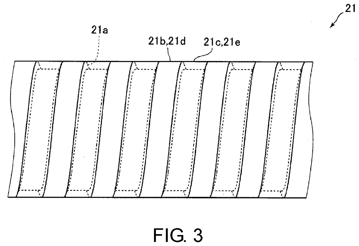
[0014]In the present disclosure, the ink adhering surface and the liquid repellent surface are preferably disposed on the same surface of the outer peripheral surface of the flattening roller. With this configuration, since the recess (depression) is not provided on the outer peripheral surface of the flattening roller, the uncured ink does not enter the recess provided on the outer peripheral surface of the flattening roller. Therefore, for example, even when the shaping apparatus includes a plurality of inkjet heads that eject different inks, it is possible to prevent different inks from being mixed when shaping the three-dimensional object.
[0016]In the present disclosure, on the outer peripheral surface of the flattening roller, the ink adhering portion and the non-ink adhering portion adjacent to each other are preferably provided in a spiral shape along an axial direction of the flattening roller. According to such a configuration, the processing of the flattening roller when forming the non-ink adhering portion on the flattening roller can be easily performed. Furthermore, when configured in such a manner, for example, when scraping off the ink adhered to the outer peripheral surface of the flattening roller by a blade similar to the blade described in Japanese Unexamined Patent Publication No. 2018-122479 described above, the tip of the blade that comes into contact with the outer peripheral surface of the flattening roller can be brought into contact with the ink adhering portion in the entire region in the circumferential direction of the flattening roller. Therefore, when the non-ink adhering portion is a liquid repellent surface, it becomes possible to prevent the liquid repellent surface from being scraped off by the tip of the blade. Moreover, when the non-ink adhering portion is a recess, it becomes possible to prevent the tip of the blade from fitting in the recess.
[0019]As described above, in the shaping apparatus of the present disclosure, when the three-dimensional object is shaped by the multi-pass method and the upper surface of the cured ink and the flattening roller are brought into contact with each other, the occurrence of shaping failures of the three-dimensional object can be suppressed.

Problems solved by technology

When shavings are produced, shavings may accumulate on the blade thus hindering the ink scraping operation of the blade and causing clogging of the suction pipe that suctions the ink stored in the storage unit with shavings, and thus may arise problems in the flattening operation of the flattening roller.
Furthermore, in a case where the upper surface of the cured ink and the flattening roller come into contact with each other, when the frictional force between the upper surface of the cured ink and the flattening roller becomes strong, for example, an abnormal vibration of the flattening roller caused by stick slip may occur and the three-dimensional object in the middle of shaping may deform.
That is, in a case where the three-dimensional object is shaped by the multi-pass method in the three-dimensional object shaping apparatus described in Japanese Unexamined Patent Publication No. 2018-122479, the upper surface of the cured ink and the flattening roller may come into contact with each other thus arising various problems, and hence shaping failures of the three-dimensional object may occur.

Method used


Image

  • Shaping apparatus
  • Shaping apparatus
  • Shaping apparatus

Examples


first modified example

[0056](First Modified Example of Flattening Roller)

[0057]FIG. 5 is a side view of the flattening roller 21 according to another embodiment of the present disclosure. FIG. 6 is an enlarged view describing a configuration of portion E in FIG. 5. FIG. 7 is a cross-sectional view describing a configuration of the flattening roller 21 shown in FIG. 5. FIGS. 8A to 10B are enlarged views describing the configuration of the flattening roller 21 according to another embodiment of the present disclosure. In FIGS. 8A to 10B, the configuration of the part corresponding to portion E of 5 is shown.

[0058]As shown in FIG. 6, a plurality of ink adhering surfaces 21b (white parts in FIG. 6) and a plurality of liquid repellent surfaces 21c (black parts in FIG. 6) formed on the outer peripheral surface of the flattening roller 21 may be arranged in a checkered pattern. That is, the ink adhering portions 21d and the non-ink adhering portions 21e may be arranged in a checkered pattern. In a modified exam...

second modified example

[0066](Second Modified Example of Flattening Roller)

[0067]In the embodiments and modified examples described above, the recess 21a may not be filled with a material having liquid repellency. In this case, the recess 21a is the non-ink adhering portion 21e, and the cured ink does not adhere to the recess 21a even if the upper surface of the cured ink and the flattening roller 21 come into contact with each other when shaping the three-dimensional object 2 by the multi-pass method. That is, in this case, the ink adhering portion 21d including the ink adhering surface 21b and the non-ink adhering portion 21e from the recess 21c are formed on the outer peripheral surface of the flattening roller 21.

[0068]In this case, even if the upper surface of the cured ink and the outer peripheral surface of the flattening roller 21 come into contact with each other when shaping the three-dimensional object 2 by the multi-pass method, a part of the cured ink will not be scraped off by the non-ink ad...


PUM

PropertyMeasurementUnit
thicknessaaaaaaaaaa
thicknessaaaaaaaaaa
outer diameteraaaaaaaaaa

Abstract

A shaping apparatus that shapes a three-dimensional object by a layered shaping method includes a shaping table on which the three-dimensional object is shaped, an inkjet head that ejects an ink toward the shaping table, and a flattening roller that removes a part on an upper surface side of the ink ejected from the inkjet head to flatten an upper surface of the ink and adjust a thickness of an ink layer. On the outer peripheral surface of the flattening roller, an ink adhering portion including an ink adhering surface to which the ink adheres when flattening the upper surface of the ink, and a non-ink adhering portion including a liquid repellent surface which is a surface having liquid repellency are provided.

Description

CROSS REFERENCE TO RELATED APPLICATIONS[0001]This application claims the priority benefit of Japanese Patent Application No. 2019-151093, filed on Aug. 21, 2019. The entirety of the above-mentioned patent application is hereby incorporated by reference herein and made a part of this specification.TECHNICAL FIELD[0002]The present disclosure relates to a shaping apparatus that shapes a three-dimensional object by a layered shaping method.DESCRIPTION OF THE BACKGROUND ART[0003]Conventionally, a three-dimensional object shaping apparatus that shapes a three-dimensional object by a layered shaping method is known (see e.g., Japanese Unexamined Patent Publication No. 2018-122479, Patent Literature 1). The three-dimensional object shaping apparatus described in Japanese Unexamined Patent Publication No. 2018-122479 includes an ejection unit, a main scan driving unit that causes the ejection unit to perform a main scan, and a shaping table on which a three-dimensional object is shaped. The ...

Claims


Application Information

Patent Timeline
Patent Type & Authority Applications(United States)
IPC IPC(8): B29C64/124B29C64/245B29C64/209B29C64/218B29C64/188
CPCB29C64/124B29C64/245B33Y30/00B29C64/218B29C64/188B29C64/209B33Y40/00B33Y10/00B22F12/63Y02P10/25
Inventor HAKKAKU, KUNIO
Owner MIMAKI ENG
Why Eureka
Try Eureka