Knee bolster device for vehicle

a technology for bolstering devices and vehicles, which is applied in the direction of vehicular safety arrangements, vehicle components, pedestrian/occupant safety arrangements, etc., can solve the problems of increasing the number of assembly hardware and components, increasing the cost, and affecting the rigidity of the bolster device, so as to prevent the bolster device from hitting the knee, the effect of improving rigidity and reducing the impa

Active Publication Date: 2017-09-05
HYUNDAI MOTOR CO LTD +1
View PDF50 Cites 1 Cited by
  • Summary
  • Abstract
  • Description
  • Claims
  • Application Information

AI Technical Summary

Benefits of technology

[0008]The present disclosure has been made in an effort to solve the above-described problems associated with prior art and to provide a knee bolster device for a vehicle, in which a continuous fiber thermoplastic (CFT), which has continuity of woven and stacked structures, is inserted into a lower crash pad panel disposed inside the vehicle to improve rigidity. A shock absorbing foam is fixed by a pocket formed on a rear surface of the lower crash pad panel, thereby preventing a knee of an occupant from further crashing toward an inside of the lower crash pad panel and reducing impact applied to the knee at the time of a vehicle collision. According to an exemplary embodiment of the present inventive concept, a knee bolster device comprises a lower crash pad panel, in which the lower crash pad panel having a composite material injection-molded thereto at a rear surface of the lower crash pad panel to improve rigidity of the lower crash pad panel. A shock absorbing foam is mounted on a rear surface of the lower crash pad panel and absorbs an impact
[0011]The composite material may be a continuous fiber thermoplastic inserted into the lower crash pad panel to improve the rigidity of the lower crash pad panel.
[0013]The knee bolster device for a vehicle according to the present disclosure prevents a knee of an occupant from additionally entering an inside of the lower crash pad panel and reduces an impact applied to the knee when the knee hits the lower crash pad panel during a vehicle collision, thereby satisfying enforced regulations for passenger safety at the time of conducting a vehicle collision test.
[0014]The knee bolster device for a vehicle according to the present disclosure reduces manufacturing cost and weight, and reduces the number of assembly processes by reducing the number of components.

Problems solved by technology

However, when an engine compartment is crushed inward, a cowl cross bar, which is mounted inside the crash pad at a lower side thereof, and a lower panel including a lower portion of the crash pad may strike a knee of the occupant.
However, the structure of the knee bolster according to the related art is complicated, and thus increases the number of assembly hardware and components and cost.

Method used


Image

  • Knee bolster device for vehicle
  • Knee bolster device for vehicle
  • Knee bolster device for vehicle

Examples


Embodiment Construction

[0027]Hereinafter, reference will now be made in detail to various embodiments of the present inventive concept, examples of which are illustrated in the accompanying drawings and described below. While the disclosure will be described in conjunction with exemplary embodiments, it will be understood that the present description is not intended to limit the disclosure to those exemplary embodiments. On the contrary, the disclosure is intended to cover not only the exemplary embodiments, but also various alternatives, modifications, equivalents, and other embodiments, which may be included within the spirit and scope of the disclosure as defined by the appended claims.

[0028]Hereinafter, an exemplary embodiment of the present inventive concept will be described with reference to the accompanying drawings so that those skilled in the technical field to which the present disclosure pertains may easily carry out the exemplary embodiment.

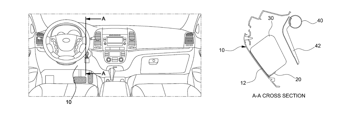
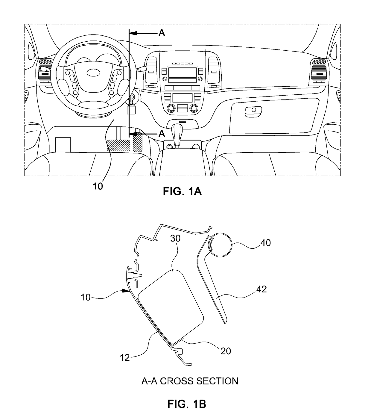
[0029]The present disclosure relates to a knee bolst...


PUM


Abstract

A knee bolster device for a vehicle includes a lower crash pad panel having a composite material injection-molded thereto at a rear surface of the lower crash pad panel to improve rigidity of the lower crash pad panel. A shock absorbing foam is mounted on a rear surface of the lower crash pad panel and absorbs an impact.

Description

CROSS-REFERENCE TO RELATED APPLICATION[0001]This application claims under 35 U.S.C. §119(a) the benefit of priority to Korean Patent Application No. 10-2014-0153448 filed on Nov. 6, 2014, the entire content of which is incorporated herein by reference.TECHNICAL FIELD[0002]The present disclosure relates to a knee bolster device for a vehicle. More particularly, the present disclosure relates to a knee bolster device for a vehicle, which is capable of satisfying enforced regulations for passenger safety at a vehicle collision test, and minimizing manufacturing costs and the number of work processes.BACKGROUND[0003]During a vehicle collision, an occupant in a vehicle may move toward a crash pad in front of the occupant by inertia, and thus, airbags and seat belts are provided in the vehicle to protect the occupant, for example, an abdominal region of the occupant. However, when an engine compartment is crushed inward, a cowl cross bar, which is mounted inside the crash pad at a lower s...

Claims


Application Information

Patent Timeline
Patent Type & Authority Patents(United States)
IPC IPC(8): B60R21/045B60R21/00
CPCB60R21/045B60R2021/0051
Inventor AN, JAE HYUN
Owner HYUNDAI MOTOR CO LTD
Why Eureka
Try Eureka