Although interesting materials, they may not be practical for airbags due to their high cost.
It is important to note that the particular formulations listed in Chen are probably poor choices for the blunting film portion of a laminated film used to make film airbags.
Thus, they will provide little resistance to the propagation of a tear in the higher modulus component of the laminated film and would be poor as the blunting layer.
Although these materials are considerably more expensive than NYLON.RTM., for example, they are about twice as strong and therefore only half as much would be required.
However, if it is laminated to a more rigid material or a net as disclosed herein and in the previous patents of the current assignee, then again many of the advantages of the material are lost since the main material providing the strength to the airbag is the more rigid film or net layer.
In contrast, many occupants are out-of-position and many real world crashes involved highly angular impacts, spinouts, rollovers etc. where the occupant only is frequently injured by the deploying airbag and impacts other objects in the vehicle compartment in addition to the airbag.
These occupant sensors will significantly reduce the number of deaths caused by airbags but in doing so, they car deprive the occupant of the protection afforded by a softer airbag if the deployment is suppressed.
However, there still will be many situations where occupants will continue to be injured in crashes where airbags could have been a significant aid.
They also must be inflated largely with the gas that is in the passenger compartment or else serious ear injuries may result and the
doors and windows may be blown out.
This would frequently subject the occupant to high accelerations, in some cases in excess of 40 Gs, and in many cases result in serious injury or death to the occupant.
However, such vehicles are usually within 10% of their unloaded-plus-one-passenger weight almost all of the time.
However, as soon as the accident commences, the traditional crash sensors will detect the accident and deploy the airbags, but for those marginal cases the occupants will have obtained little relative
forward velocity anyway and probably not be hurt and certainly not killed by the deploying
plastic film airbags which stop deploying as soon as the occupant is contacted.
Although such coatings are films, they differ significantly from the films disclosed herein in that they do not significantly modify the properties of the fabric airbags to which they are applied.
Such an inflated airbag would protrude significantly into the passenger compartment from the
steering wheel and, in most cases,
impact and injure the driver.
Moreover, the above-mentioned method of manufacturing an airbag involves a great deal of sewing and thus is highly labor intensive and, as a result, a large percentage of all driver airbags are presently manufactured in low labor cost countries such as Mexico.
However, most occupants are not positioned at the ideal location assumed by the airbag
system designer, and also may not have the dimensions, e.g., size and weight, in the range considered for optimum
airbag deployment by the airbag
system designer.
Many occupants sit very close to the airbags, or at least closer than expected by the airbag
system designer, and as mentioned above, are injured by the
airbag deployment.
In addition, as mentioned above, some occupants sit very far from the
steering wheel or instrument panel and, with conventional airbags, a significant distance remains between the occupant and the inflated airbag.
This effect serves to both increase the design strength requirements of the airbag and increase the injury induced in the occupant by the airbag.
This imposes several limitations on the restraint system that encompasses the airbag system.
If the driver has lost control of the car and is traveling at 30 MPH, for example, and has a secondary
impact one second or about 50 feet later, this time with a large tree, the airbag will have become deflated and thus is not available to protect the occupant in this secondary, life threatening impact.
In other situations, the occupant might be involved in an accident that exceeds the design capability of the restraint system.
At higher velocities, the maximum chest deceleration experienced by the occupant can exceed 60 G's and become life threatening.
This is particularly a problem in smaller vehicles, where airbag systems typically only marginally meet the 60-G maximum requirement, or with larger or frailer occupants.
There are many cases, particularly in marginal crashes, where existing crash sensors will cause the airbag to deploy late in the crash.
This can also result in an "out-of-position occupant" for deployment of the airbag that can cause injuries and possibly death to the occupant.
The deploying airbag in these situations can
cause injury or death to the out-of-position occupant.
It is estimated that more than one hundred people have now been killed and countless more seriously injured by the deployment of the airbag due to being out-of-position.
This, of course, increases the cost of the airbag system as well as its size, weight, pressure in the passenger compartment and total amount of contaminants resulting from the gases that are exhausted into the automobile environment.
This then requires an even larger inflator which, in many cases, cannot be accommodated in conjunction with the
steering wheel, if conventional inflator technology, rather than an aspirated inflator, is utilized.
Currently used passenger side airbags have sufficient force to cause significant injury to a child sitting in such a seat and parents are warned not to use child seats in the front seat of a vehicle having a passenger side airbag.
Additionally, several automobile companies are now experimenting with rear seat airbags in which case, the child seat problem would be compounded.
Many films are quite inelastic under typical stresses associated with an
airbag deployment.
Films having this inelastic quality, that is films with a high modulus of elasticity and low elongation at failure, tend to propagate
tears easily and thus when used alone are not suitable for airbags.
Such films, on the other hand, do not form the flat ellipsoidal shape desired for steering wheel-mounted driver side airbags.
Adding holes, however, reduces the tensile strength of the material by a factor of two or more due to the
stress concentration effects of the hole.
It also reduces the amount of available material to
resist the stress.
Also, Kokeguchi does not disclose any particular shapes of film airbags or even the airbag itself for that matter.
It is also noteworthy that Kokeguchi discloses that vacuum methods can be used to form the airbag into the desired shape and thus fails to realize that the properties of inelastic film results in the airbag automatically forming the correct shape upon deployment.
Also noteworthy is that Kokeguchi states that polymeric films do not have sufficient edge
tear resistance and thus fails to realize that films can be so formulated to have this property, particularly those made incorporating elastomers.
These limitations of Kokeguchi results in a very thick airbag that although comprised of film
layers, no longer qualifies as a true film airbag as defined herein.
Also, not all
sodium azide inflators produce significant quantities of hot particles.
One interesting point that also is not widely appreciated by those skilled in the art previously, is that the gas temperature from the inflator is only an issue in the choice of airbag materials during the initial stages of the inflation.
However, substantial pressure is still required to open the deployment door.
This rapid deployment can put excessive stresses on the film airbag and increases the chance that the occupant will be injured thereby.
The discussion of the self-shaping airbag thus far has been limited to film airbags.
Naturally, this is wasteful of material and attempts have been made to redesign the airbag to optimize its design in order to more closely equalize the
stress distribution and permit a reduction in fabric strength and thus thickness and weight.
However, this optimization process when used with conventional fabric airbags can lead to more complicated
assembly and sewing operations and more expensive woven materials and thus higher overall manufacturing costs.
An example of such an airbag is that marketed by Precision Fabrics of Greensboro, N.C. Thus, there is a tradeoff between manufacturing cost and airbag optimization.
First, other than tooling cost, the manufacturing cost of an optimized airbag is no greater than for a non-optimized airbag and in fact frequently less since less material is required.
The film used is relatively rigid and has difficulty adjusting to form a spherical shape.
One problem with film balloons is that when a hole is formed in the
balloon, it fails catastrophically.
Most of these applications are more difficult to solve or unsolvable using conventional sewing technology.
Such materials frequently exhibit blunting.
There is no known prior art covering passenger airbags made from
plastic film.
Further injuries occur when the occupant's lower
torso and legs move forward such that the knees are trapped in or beneath the instrument panel just before the foot well begins to collapse.
As the foot well collapses, it pushes the occupant's feet backward, causing the knees to elevate and become further trapped.
As the foot well continues to crush, the loads on the trapped legs increase and cause foot,
ankle, and
tibia injuries.
However, depending on the design of the vehicle seat and force of the collision, there is a tendency for an occupant to slide forward along the seat and slip below the primary airbag, sometimes even entering into leg compartment of the vehicle.
When the occupant submarines, the primary airbag is less effective in protecting the occupant.
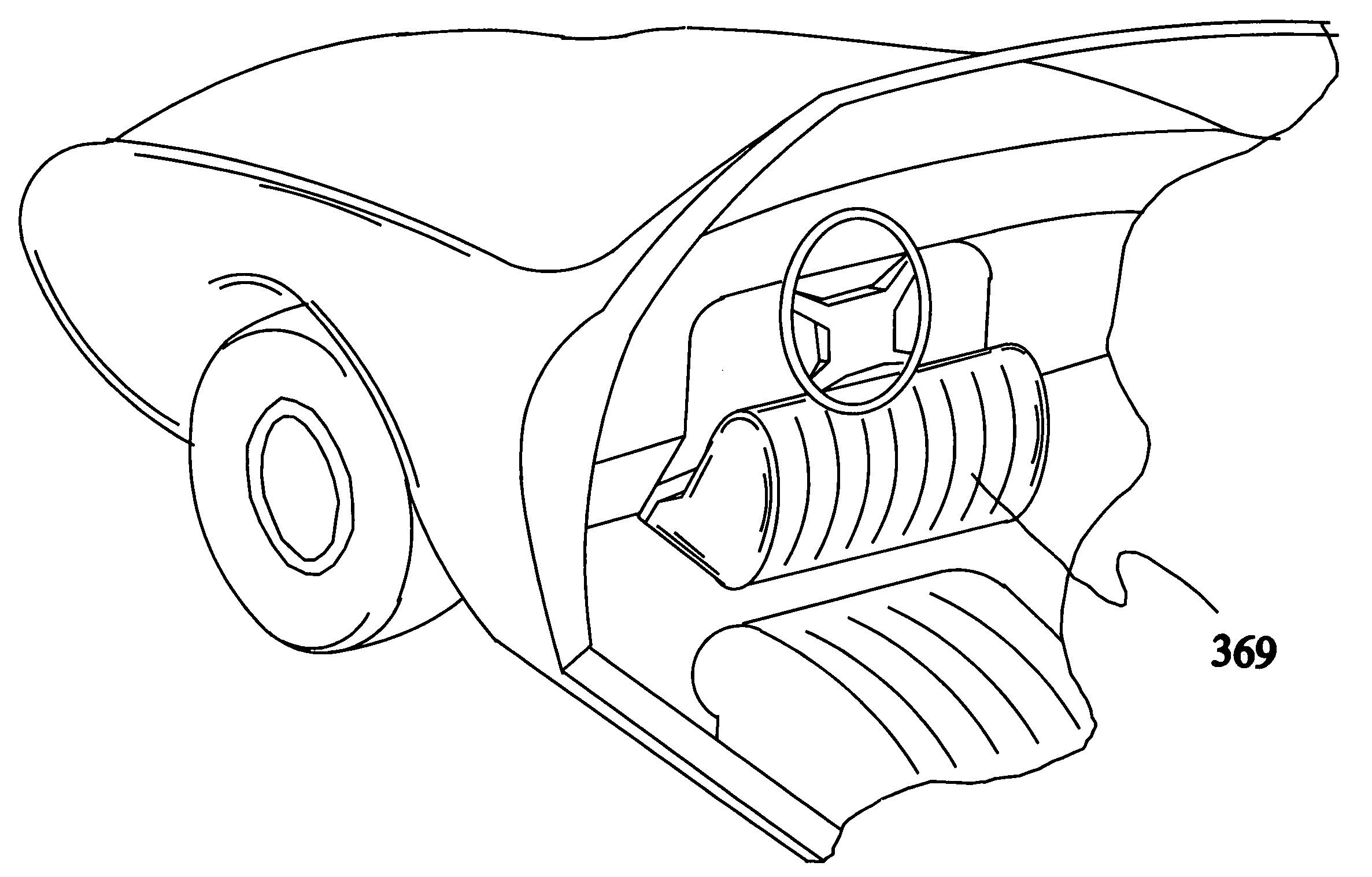
In an accident in a sports car, the knees of the occupant often strike the instrument panel.
Traditional designs of the knee airbag without the
load distribution plate have been less successful in preventing submarining.
This is due to the fact that the airbag only partially fills the volume surrounding the knees and legs of the occupant and thus the airbag can easily deform and provides less support.
On the other hand, it is possible for the knees of the occupant to slip off of the
load distribution plate thereby defeating its purpose.
Also, if the
load distribution plate is at a significant distance from the occupant's knees, the occupant can attain a significant velocity before striking the plate resulting in knee and
femur injuries.
The '366 patent correctly points out that a knee
bolster airbag, referred to in the '366 patent as a reactive type knee
bolster, functions on the principle of a
single compartment airbag and has the
disadvantage that on impact of the knees with the airbag, the airbag loses rigidity in the
impact area.
This patent points out that using known knee bolsters, the knees of an improperly seated occupant can slide off the knee
bolster potentially increasing the tendency of the occupant to
submarine under the instrument panel.
Another problem pointed out by the '836 patent is the tendency, due to the point loading, for the knees in many airbag knee bolsters to penetrate too far into the bolster and therefore lose some of the
energy absorbing effects.
There is also a danger that if punctured the '871 knee bolster will pop as a
balloon since it will not exhibit blunting as described below.
Again this design suffers from the tendency of the occupant's knees to slide off of the bolster if the accident is from an angle or if the occupant is not properly seated.
In contrast to some pertinent inventions disclosed below, the junction points and lines do not enable the formation of an airbag having a plurality of substantially straight or elongate compartments, or even a multiplicity of cells, which can be deploy along the side of a vehicle in order to protect the occupant(s) from injury.
There also is no prior art for making a side curtain airbag from
plastic film.
However, to achieve this ideal would require many tethers since left to its own, the airbags would tend to form spherical-like chambers.
There is minimal, if any, prior art for exterior mounted airbags made from plastic film.
To date, barrier coatings have not been commercially applied in airbags made of fabric and in particular side curtain airbags made of fabric which is often permeable.
It is disadvantageous that current
polymer coatings used on such airbags are relatively thick thereby increasing the
mass of the airbag making it difficult to pack into a ceiling space and
delay the deployment of the airbag in an accident, thereby increasing the chance that an occupant will not receive the full benefit of the airbag.
As a result of these disadvantages, such coatings are not optimal for use on side curtain airbags.
Much of the leakage in side curtain airbags occurs through the seams where the front and rear panels forming the side curtain airbag are joined.
However, the effective
aspect ratio of these fillers is much lower when incorporated into a binder and is directly related to the barrier improvement due to the
platelet filler, generally resulting in reduced barrier properties.

