Display device

a display device and image technology, applied in the field of display devices, can solve the problem of insufficient contrast of images to be observed by observers, and achieve the effect of reducing the weight of the display device and deteriorating the display quality of images

Active Publication Date: 2017-09-05
SONY CORP
View PDF117 Cites 24 Cited by
  • Summary
  • Abstract
  • Description
  • Claims
  • Application Information

AI Technical Summary

Benefits of technology

[0028]In the display device according to the first aspect of the present disclosure, the light shielding member configured to shield incidence of external light on the optical device is disposed in the region of the optical device on which light output from the image forming device is incident. Thus, even when there is a change in an amount of incident external light caused by an operation of the dimmer, the external light is not incident on the region of the optical device on which light output from the image forming device is incident, and thus generation of unwanted stray light or the like and deterioration of display quality of an image in the display device do not occur. In addition, in the display device according to the second aspect of the present disclosure, since the first substrate constituting the dimmer also serves as a constituent member of the optical device, a reduction of a whole weight of the display device can be attained, and there is no concern of causing discomfort to a user of the display device.

Problems solved by technology

However, due to extreme brightness of the environment around the position in which the image display device 100′ or 300′ is placed or the content of an image being displayed, a problem that sufficient contrast is not given to an image to be observed by an observer can occur.

Method used


Image

  • Display device
  • Display device
  • Display device

Examples


embodiment 1

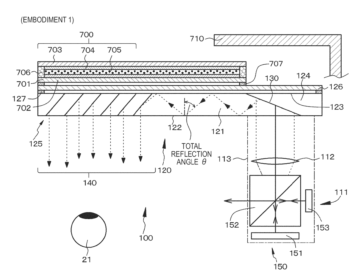
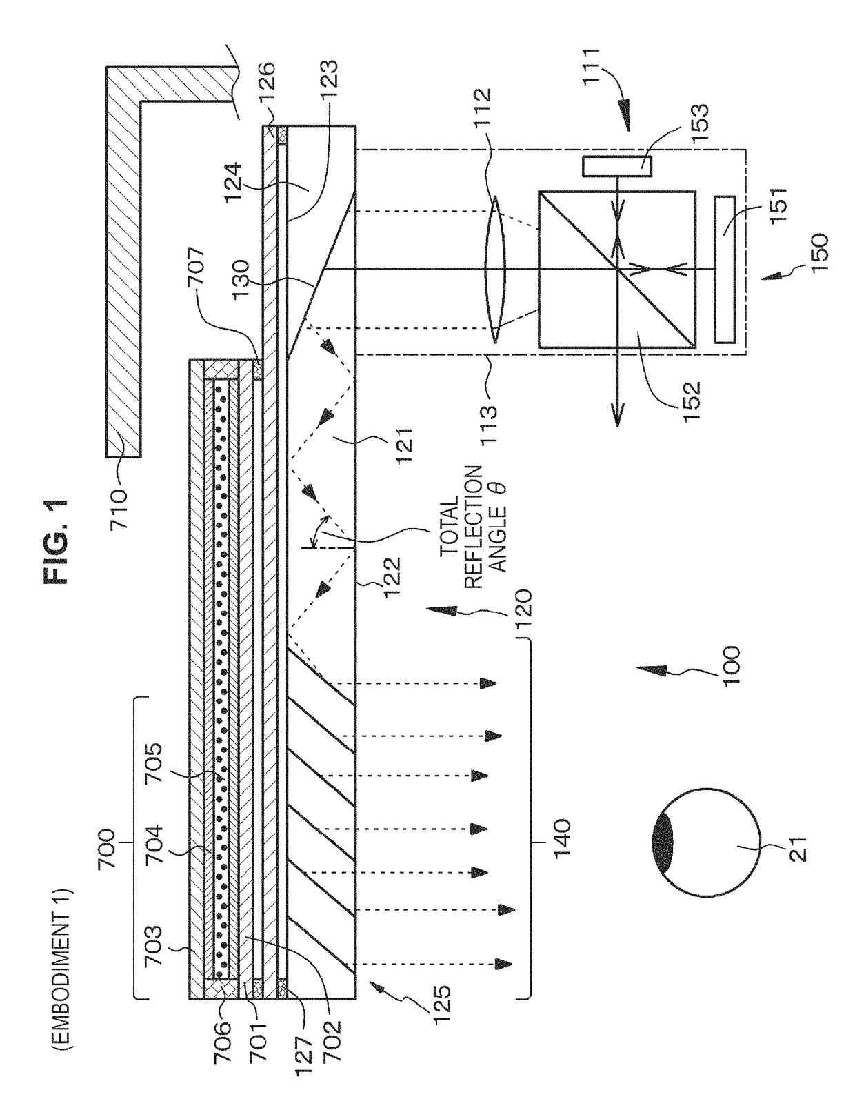
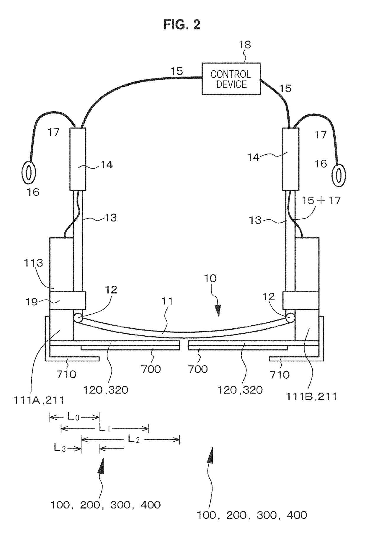
[0197]Embodiment 1 relates to a display device according to a first aspect of the present disclosure. FIG. 1 shows a conceptual diagram of an image display device of Embodiment 1, FIG. 2 shows a schematic diagram of the display device of Embodiment 1 (specifically, a head mounted type display device or HMD) as viewed from above, FIG. 3A shows a schematic diagram thereof as viewed from a side, FIG. 3B is a schematic diagram of the portion of an optical device and a dimmer as viewed from a front side, and FIGS. 4A and 4B show schematic cross-sectional diagrams of the dimmer schematically showing an operation of the dimmer in the display device of Embodiment 1. Note that, in FIG. 3A, a light shielding member is indicated by dashed lines.

[0198]The display device of Embodiment 1 or Embodiment 2 to Embodiment 11 that will be described below includes:

[0199](a) an eyeglass-shaped frame 10 mounted on the head of an observer (for example, a spectator); and

[0200](b) an image display device 100...

embodiment 2

[0221]Embodiment 2 is a modification of Embodiment 1. As in a conceptual diagram shown in FIG. 5, in the display device of Embodiment 2, a light shielding member 720 is disposed in a portion of the optical device 120 on the side opposite to the side on which the image forming device 111A or 111B is disposed, unlike in Embodiment 1. To be specific, the light shielding member 720 can be formed by printing non-transparent ink on the optical device 120 (specifically, an inner face of the protective member 126). Except for this point, the display device of Embodiment 2 has the same configuration and structure as the display device of Embodiment 1, and thus detailed description thereof will be omitted. Note that the light shielding member 720 of Embodiment 2 and the light shielding member 710 of Embodiment 1 can be combined. Note that the light shielding member 720 may be formed on an outer face of the protective member 126.

embodiment 3

[0222]Embodiment 3 is also a modification of Embodiment 1. As in a conceptual diagram shown in FIG. 6 or FIG. 7, in the display device of Embodiment 3, a light shielding member 730 is disposed in the dimmer 700, unlike in Embodiments 1 and 2. To be specific, the light shielding member 730 can be formed by printing non-transparent ink in the dimmer 700. Note that, in the example shown in FIG. 6, the light shielding member 730 is formed on an outer face of the first substrate 701 of the dimmer 700, and in the example shown in FIG. 7, the light shielding member 730 is formed on an inner face of the first substrate 701 of the dimmer 700. Except for this point, the display device of Embodiment 3 has the same configuration and structure as the display device of Embodiment 1, and thus detailed description thereof will be omitted. Note that the light shielding member 730 of Embodiment 3 and the light shielding member 710 of Embodiment 1 can be combined, the light shielding member 730 of Emb...


PUM


Abstract

There is provided a display device including (I) an eyeglass-shaped frame configured to be mounted on a head of an observer, and (II) an image display device attached to the frame. The image display device includes (A) an image forming device, and (B) an optical device on which light output from the image forming device is incident, in which the light is guided, and from which the light is output. A dimmer configured to adjust an amount of external light incident from outside is installed on a side opposite to a side on which the image forming device of the optical device is disposed. A light shielding member configured to shield incidence of external light on the optical device is disposed in a region of the optical device on which light output from the image forming device is incident.

Description

CROSS REFERENCES TO RELATED APPLICATIONS[0001]The present invention is the National Stage of International Application No. PCT / JP2012 / 082461, filed in the Japanese Patent Office as a Receiving Office on Dec. 14, 2012, and claims the priority benefit of Japanese Patent Application Number 2012-012244, filed in the Japanese Patent Office on Jan. 24, 2012, which is hereby incorporated by reference to the maximum extent allowable by law.TECHNICAL FIELD[0002]The present disclosure relates to a display device, and more specifically, relates to a display device using a head mounted type display (HMD or Head Mounted Display).BACKGROUND ART[0003]In recent years, augmented reality technology (AR technology: Augmented Reality) in which a virtual object or various kinds of information serving as supplementary information is combined with a real environment (or a part thereof) and then presented as electronic information has been focused on. In order to realize the augmented reality technology, f...

Claims


Application Information

Patent Timeline
Patent Type & Authority Patents(United States)
IPC IPC(8): G02B27/01G02B27/28G02B26/10G02B26/08
CPCG02B27/0172G02B26/0833G02B26/101G02B27/017G02B27/283G02B2027/0105G02B2027/0118G02B2027/0174G02B2027/0178
Inventor MACHIDA, AKIOSAKAMOTO, YUKINARI
Owner SONY CORP
Why Eureka
Try Eureka