Display device

Inactive Publication Date: 2005-08-04
SHARP KK
View PDF7 Cites 59 Cited by
  • Summary
  • Abstract
  • Description
  • Claims
  • Application Information

AI Technical Summary

Benefits of technology

[0045] According to the present invention, deterioration of display quality, which would be cau

Problems solved by technology

Even with other display examples, such as a human face, plain (patternless) wallpaper, or the like, vertical stripes (vertical lines) occur over the entire screen, resulting in deteriorated display quality.
However, in the case of a television monitor for personal use which is also used as a monitor of a PC (personal computer), the viewing distance between a viewer and the display device becomes relatively short.
Thus, in the case where the viewing distance is set according to the purpose of the display device, the display quality is deteriorated by the stripe pattern unless the resolution is equal to or higher than a certain level.
Thus, vertical stripes are v

Method used


Image

  • Display device
  • Display device
  • Display device

Examples


embodiment 1

[0061]FIG. 3 is a schematic partial cross-sectional view showing a liquid crystal display device of embodiment 1. The liquid crystal display device includes a liquid crystal panel, a driver circuit section for driving the liquid crystal panel, a backlight (if the liquid crystal display device is a transmissive LCD), etc. The liquid crystal panel includes a TFT (Thin Film Transistor) substrate 10, a CF (color filter) substrate 11 which faces the TFT substrate 10, a perimeter sealing member 12 interposed between the substrates 10 and 11, a liquid crystal layer 13 interposed between the substrates 10 and 11 and enclosed by the perimeter sealing member 12, and a pair of polarization plates 14 and 15 attached on the external surfaces of the substrates 10 and 11, respectively.

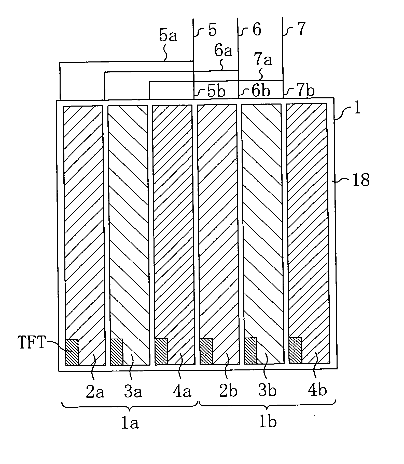
[0062] The TFT substrate 10 includes a plurality of scanning lines (not shown) extending in the row direction, a plurality of signal lines 5, 6 and 7 extending in the column direction to cross the scanning lines, TF...

embodiment 2

[0090] In a liquid crystal display device of the present invention, a sub-pixel which is interposed between signal lines of the same polarity may have a different aperture ratio from that of another sub-pixel of the same color included in the same pixel. For example, in the case where the aperture ratio of a sub-pixel interposed between signal lines of the same polarity is relatively high, occurrence of a black line is suppressed in a normally black mode display device. In the case where the aperture ratio of a sub-pixel interposed between signal lines of the same polarity is relatively low, occurrence of a bright line is suppressed in a normally white mode display device.

[0091]FIG. 9 shows a general structure of a pixel of a liquid crystal display device of embodiment 2. It should be noted that, in FIG. 9 and subsequent drawings, components having substantially the same functions as those of the liquid crystal display device of embodiment 1 are denoted by the same reference numera...

embodiment 3

[0094] In the examples described in embodiments 1 and 2, each of the sub-pixel groups 1a and 1b is formed by sub-pixels 2, 3 and 4 of three colors, red, green and blue. However, according to the present invention, the hues of the sub-pixels are not limited to the above. In an example of embodiment 3, each of the sub-pixel groups 1a and 1b is formed by sub-pixels of other three colors, cyan, magenta and yellow.

[0095]FIG. 10 shows a general structure of a pixel of a liquid crystal display device of embodiment 3 where the polarity of each sub-pixel included in the pixel is shown. Also in embodiment 3, each pixel 1 is formed by two sub-pixel groups 1a and 1b which are adjacent to each other in the row direction as in embodiments 1 and 2. Each of the sub-pixel groups 1a and 1b includes sub-pixels 22, 23 and 24 of three colors, yellow, cyan and magenta, which are periodically aligned in one direction (in the row direction in this example). Specifically, first and second yellow sub-pixels...


PUM


Abstract

A display device includes a plurality of pixels arranged in a matrix. At least one of the pixels includes two sub-pixel groups. Each of the sub-pixel groups includes sub-pixels of three or more colors. Sub-pixels of the same color in each pixel are driven by the same signal.

Description

CROSS-REFERENCE TO RELATED APPLICATIONS [0001] This Nonprovisional application claims priority under 35 U.S.C. §119 (a) on Patent Applications No. 2003-435257 filed in Japan on Dec. 26, 2003 and No. 2004-332195 filed in Japan on Nov. 16, 2004, the entire contents of which are hereby incorporated by reference. BACKGROUND OF THE INVENTION [0002] 1. Field of the Invention [0003] The present invention relates to a display, such as a liquid crystal display (LCD) device, a plasma display panel (PDP), an inorganic or organic electroluminescence (EL) display device, a light emitting diode (LED) display device, a fluorescence display tube, a field emission display device, an electrophoretic display device, an electrochromic display device, a cathode ray tube (CRT) display device, or the like. [0004] 2. Description of the Prior Art [0005] The flat panel display (hereafter, referred to as “FPD”), such as a liquid crystal display, a plasma display, an EL display, or the like, has pixels arrange...

Claims


Application Information

Patent Timeline
IPC IPC(8): G02F1/133G09F9/30G09G3/20G09G3/36
CPCG09G3/2003G09G2320/02G09G2300/0452G09G3/3648
Inventor HIRATA, MITSUAKITAKEUCHI, MASANORI
Owner SHARP KK
Why Eureka
Try Eureka