Implant system with polymeric insert and two tray options

a technology of polymer inserts and implants, applied in the field of orthopaedic prosthesis, can solve the problems of weak cement-less bonding, system falling out of favor, and high cost of systems

Active Publication Date: 2017-09-12
HOWMEDICA OSTEONICS CORP
View PDF11 Cites 5 Cited by
  • Summary
  • Abstract
  • Description
  • Claims
  • Application Information

AI Technical Summary

Problems solved by technology

Although the system was resistant to stress shielding and had a long in vivo survival rate, the system fell out of favor with the medical industry because it was difficult to implant into the patient and because the bond between UHMWPE and bone with bone cement is not as strong as the bond with metal.
Although the two-part system made the device much easier to implant, the system was expensive.
Thus far, clinical results have shown that the cement-less bond is weaker than a bond using bone cement.
In addition, devices comprising polymer-metal composites are expensive to manufacture.

Method used


Image

  • Implant system with polymeric insert and two tray options
  • Implant system with polymeric insert and two tray options
  • Implant system with polymeric insert and two tray options

Examples


Embodiment Construction

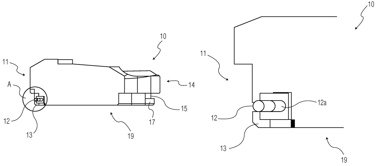
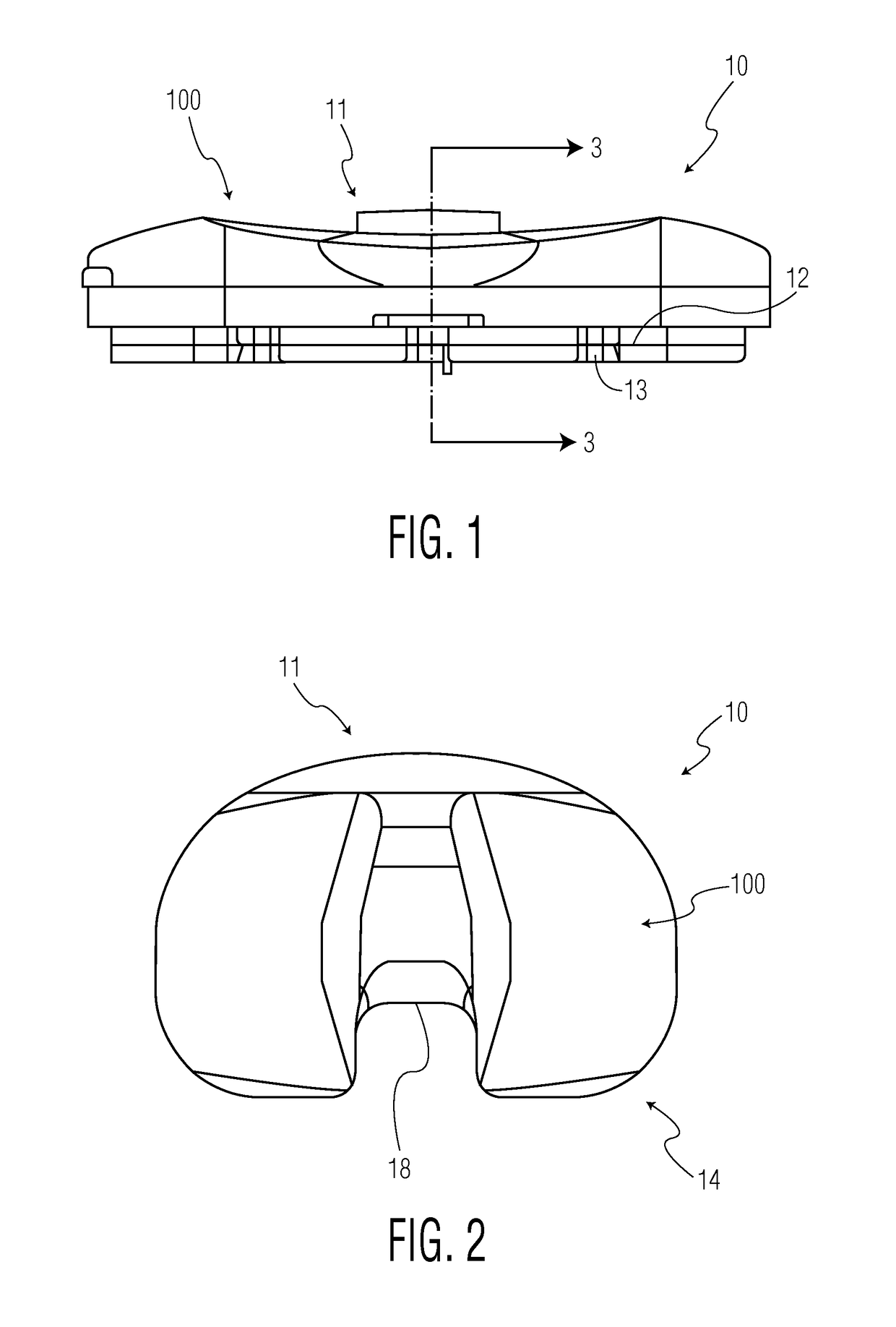
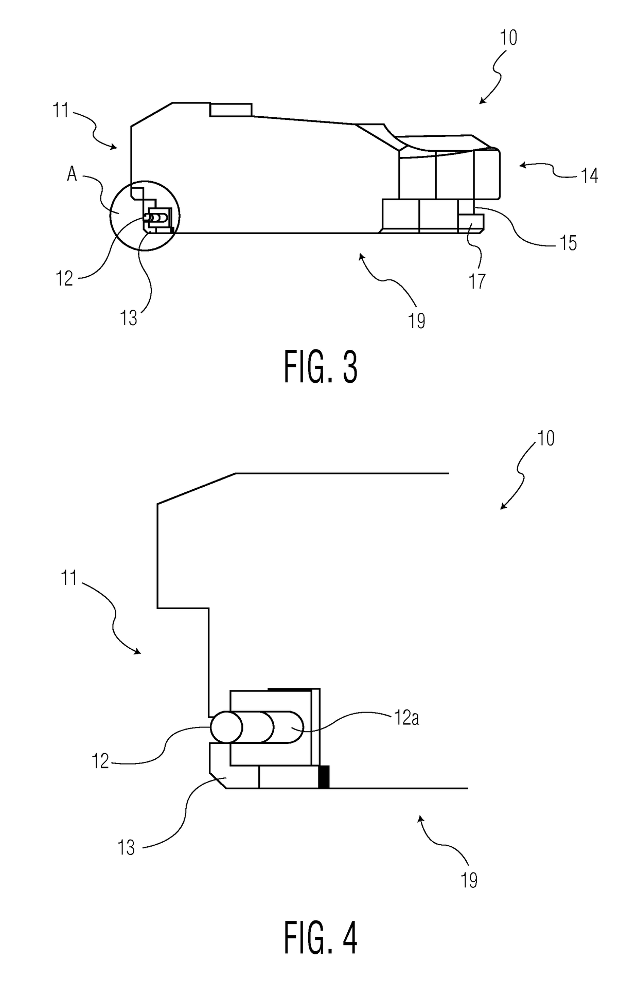
[0021]FIGS. 1 and 2 illustrate a representative UHMWPE tibial bearing insert according to the present invention, generally denoted as 10. The tibial insert 10 comprises an anterior surface 11 including a locking wire 12 and locking tab 13 and a posterior surface 14 including an intracondylar recess 18 and locking recesses 15, shown in FIG. 3 (not in FIG. 2). The insert also has a bearing surface 100. In an alternative embodiment, an additional locking recess 15 may be placed within the intracondylar recess 18. Locking recess 15 engages a protrusion 24a, 34a formed on the posterior surfaces 23, 33 of the tibial trays 20, 30 as shown in FIGS. 5 and 9.

[0022]FIGS. 3 and 4 illustrate a cross-sectional view of the tibial insert 10 along line 3-3 of FIG. 1. Referring to FIG. 3, the locking wire 12 is located above the locking tab 13 along the anterior surface 11, whereas the locking recess 15 is disposed along the lower portion of the posterior surface 14.

[0023]FIG. 4 is an enlarged view o...


PUM


Abstract

A tibial implant system has an ultra-high molecular weight polyethylene tibial insert which can engage with either one of two tibial trays through differing means of engagement. The tibial insert includes a locking wire and locking tab disposed along an anterior surface and a locking recess disposed along a posterior surface. A first polymeric tibial tray includes a bead along an anterior wall and an undercut area along a posterior wall. A second metallic tibial tray includes a plurality of barbs along an anterior wall and an undercut area along a posterior wall.

Description

BACKGROUND OF THE INVENTION[0001]The present invention relates to an orthopedic prosthesis utilized in knee joint replacements. More particularly, the present invention is directed to a tibial implant system comprising a tibial insert and interchangeable tibial trays, one made of a metal and one made of a polymer.[0002]Knee arthroplasty is a well-known surgical procedure to replace the weight-bearing surfaces of the knee joint to relieve pain and disability. It has enabled many individuals to function normally where it otherwise would be impossible. Artificial joints usually comprise metallic, ceramic, or plastic components implanted into existing bone.[0003]In a typical procedure, a tibial tray or baseplate is mounted on a prepared proximal tibia of a patient and a tibial bearing insert is mounted on the tibial tray. Methods and corresponding tibial trays exist that allow for implantation into the tibia with or without the use of bone cement.[0004]Earlier designs of tibial implant ...

Claims


Application Information

Patent Timeline
Patent Type & Authority Patents(United States)
IPC IPC(8): A61F2/38A61F2/30
CPCA61F2/389A61F2002/30616
Inventor DONG, NICHOLAS NAI GUANGPOGGIE, MATTHEW P.SCHMIDT, WALTER
Owner HOWMEDICA OSTEONICS CORP
Why Eureka
Try Eureka