Spine stabilization device, and method and kit for its implantation

a stabilizing device and spine technology, applied in the field of spine stabilization devices, can solve the problems of compromising the stability of the vertebral body, weakening the cortical bone of the endplate, and limited access to apply instruments, and achieve good, reliable anchoring

Active Publication Date: 2010-10-28
SPINEWELDING
View PDF65 Cites 98 Cited by
  • Summary
  • Abstract
  • Description
  • Claims
  • Application Information

AI Technical Summary

Benefits of technology

[0064]It has been found that by the approach according to the fifth aspect of the invention, a good, reliable anchoring may be achieved. Moreover, the angle in projection onto the sagittal plane (in the following termed “the sagittal angle”) may be comparably small. Nonzero angles less than 40°, less than 30° or even less than 20° to the median plane are possible, for example between 4° and 30° or between 4° and 18° to the median plane, or between 6° and 16° to the median plane; preferably the sagittal angle of the upper and lower fasteners, with respect to each other is between 8° and 36°, where also an asymmetric arrangement (for example with the angle of the lower fasteners to the median plane being 0° and the angle of the upper fasteners to the median plane being 8° or more) is possible.
[0065]This features the advantage that a straight approach to the implantation site while without an

Problems solved by technology

Furthermore, precautions are necessary to fix the screws in the anterior wall of the spacer or cage in such a way that the screw heads do not protrude outwards of the anterior wall of the cage and that the screws cannot loosen to avoid damaging the major blood vessels that run along the anterior portion of the spine.
Driving the fixation means through the endplates may weaken the cortical bone of the endplates, compromising the stability of the vertebral bodies.
This may be problematic if the bone quality is already weakened by degenerative osteoporosis or traumatic injury or if multiple attempts for the fixation are required durin

Method used


Image

  • Spine stabilization device, and method and kit for its implantation
  • Spine stabilization device, and method and kit for its implantation
  • Spine stabilization device, and method and kit for its implantation

Examples


Embodiment Construction

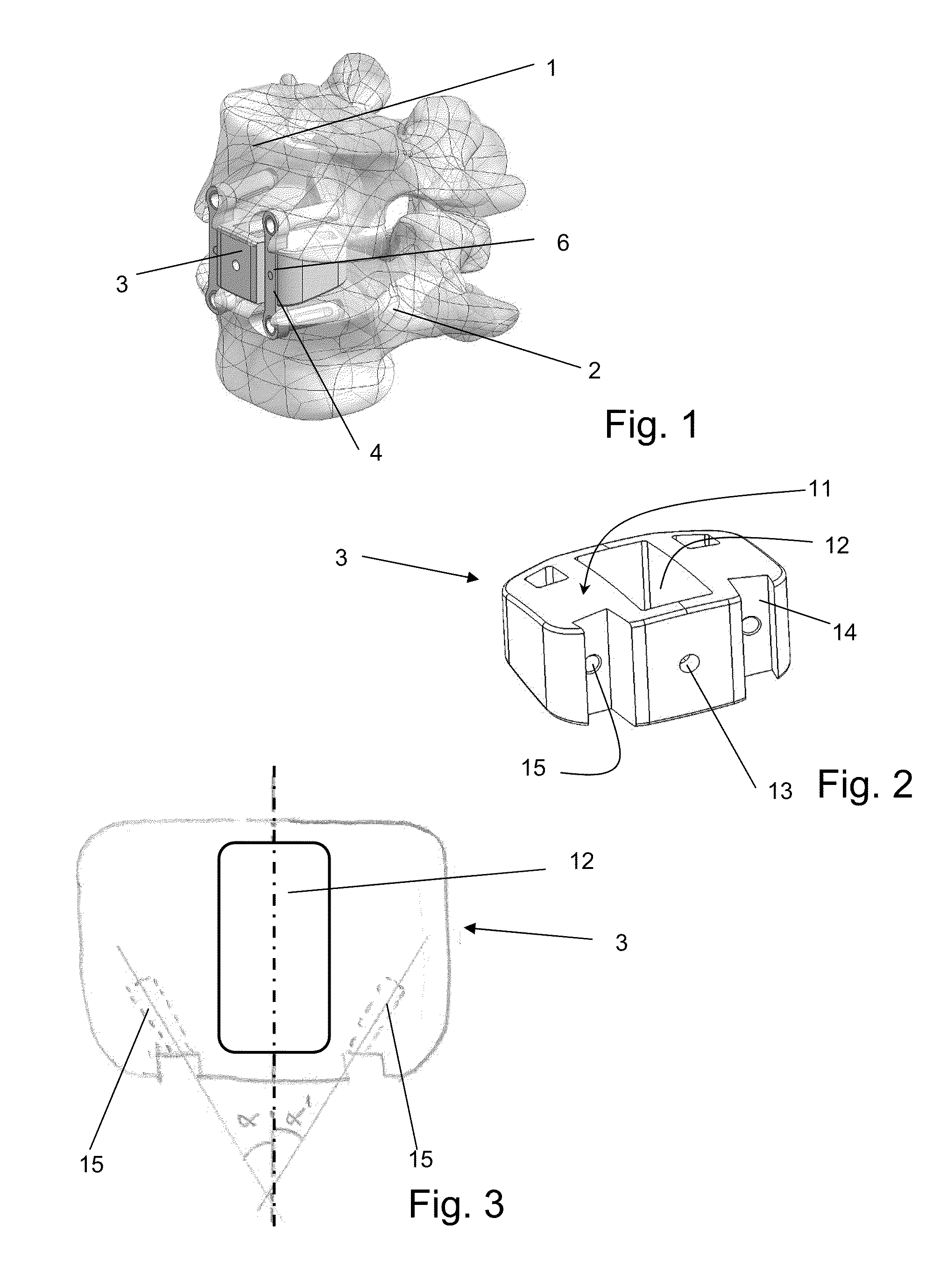
[0173]FIG. 1 depicts an embodiment of a spine stabilization device inserted in a human spine. More concretely, the figure shows an upper vertebra 1 and a lower vertebra 2, between which the intervertebral disc has been at least partly removed. The device comprises an interbody spacer 3 between the vertebral body of the upper vertebra and the lower vertebra. The interbody spacer serves as a distance holder between the upper and the lower vertebral body. The interbody spacer after the surgical insertion between the vertebral bodies is held in place by two fixation devices 4. The fixation devices 4 each comprise two anchors anchoring them in the upper and the lower vertebral body respectively. Further, they each comprise a support portion 6 securing the interbody spacer 3 against movement towards the ventral direction.

[0174]FIGS. 2 and 3 depict the interbody spacer 3 in somewhat more detail. The interbody spacer may be made of any suitable material including PEEK, potentially coated by...


PUM

PropertyMeasurementUnit
Timeaaaaaaaaaa
Electric energyaaaaaaaaaa
Angleaaaaaaaaaa

Abstract

A spine stabilization device is provided, the spine stabilization device including an interbody spacer shaped to be inserted between a vertebral body of an upper vertebra and a vertebral body of a lower vertebra, and including a top surface oriented towards the lower endplate of the vertebral body of the upper vertebra and a bottom surface oriented towards the upper endplate of the vertebral body of the lower vertebra; and a fixation device to be inserted after placement of the interbody spacer, the fixation device including a support portion securing the interbody spacer against escaping from between the vertebral bodies of the upper and lower vertebra into a ventral direction, the support portion shaped to rest against a portion of an anterior surface of the interbody spacer, and further including an anchor, the anchor including an anchoring material portion that is configured to be inserted, in a liquid state, into cancellous bone tissue of at least one of the vertebral body of the upper vertebra and of the vertebral body of the lower vertebra, to thereby infiltrate the cancellous bone tissue, and to harden thereafter so as to fix the support portion to the vertebral body.

Description

FIELD OF THE INVENTION[0001]The invention relates to a spine stabilization device used in spinal surgery as a spacer in place of a degenerated or injured intervertebral disc between two adjacent vertebral bodies for permanent fusion of two vertebrae. The invention further relates to kits of instruments for implantation of the spine stabilization device, and to methods of implanting the device.BACKGROUND OF THE INVENTION[0002]In the prior art, such implant systems which function as spacers between adjacent vertebral bodies to be fused and replace injured or degenerated intervertebral discs are known:[0003]U.S. Pat. No. 7,077,864 describes an example of a vertebral interbody cage that can be implanted from an anterior, posterior, anteriolateral or lateral position. A cage is an example of a vertebral interbody spacer and spine stabilizer. The cage is filled with bone graft or bone growth promoting material, which promotes the fusion of the vertebrae for long term stability. Advantageo...

Claims


Application Information

Patent Timeline
IPC IPC(8): A61F2/44A61B17/56A61B17/84
CPCA61B17/7059A61F2310/00796A61B17/864A61B17/8822A61B17/8836A61F2/442A61F2/447A61F2002/2835A61F2002/30387A61F2002/30401A61F2002/30578A61F2002/30598A61F2002/30736A61F2002/30785A61F2002/30904A61F2002/4475A61F2002/4602A61F2002/4627A61F2002/4628A61F2002/4629A61F2220/0025A61F2310/00023A61F2310/00179A61B17/7098A61F2220/0008A61F2002/30594A61F2/4601A61F2002/30593
Inventor MUELLER, ANDREABERRA, MILICAAESCHLIMANN, MARCELLEHMANN, MARIOWEBER, URSMAYER, JORGHOCHSCHULER, STEPHENYUAN, HANSENPHILLIPS, FRANK M.MEHL, STEPHANIEMOCK, ELMARWENGER, ANDREASSEILER, PHILIPPBERLEMANN, ULRICH
Owner SPINEWELDING
Why Eureka
Try Eureka