
Ophthalmic lens having an optical zone blend design

a technology of optical zone and blend design, applied in the field of ophthalmic lenses, can solve problems such as ghost images to the wearer, and achieve the effect of reducing the appearance of ghost images or image blur

Active Publication Date: 2006-02-28
ALCON INC
View PDF13 Cites 94 Cited by
  • Summary
  • Abstract
  • Description
  • Claims
  • Application Information

AI Technical Summary

Benefits of technology

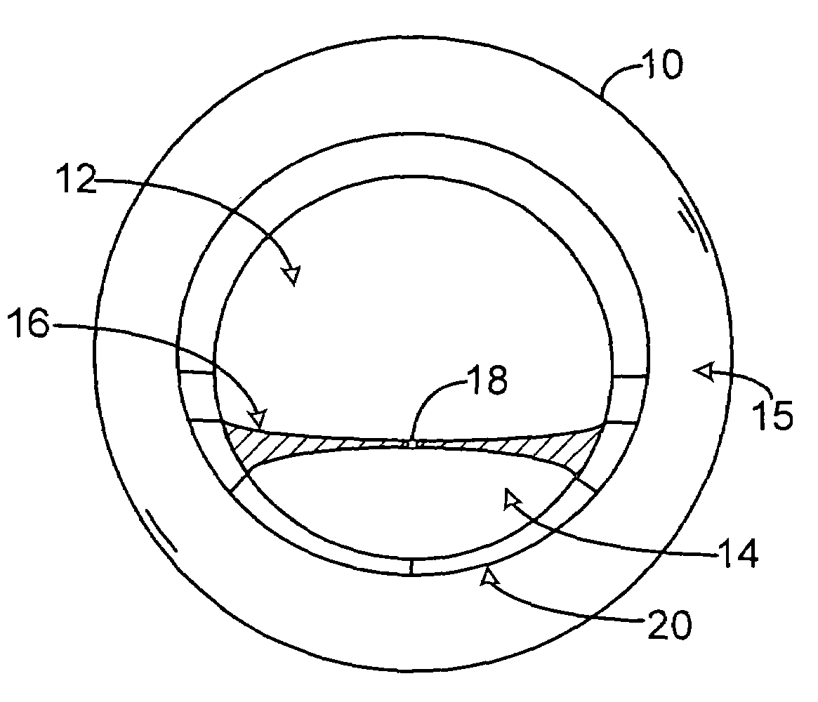
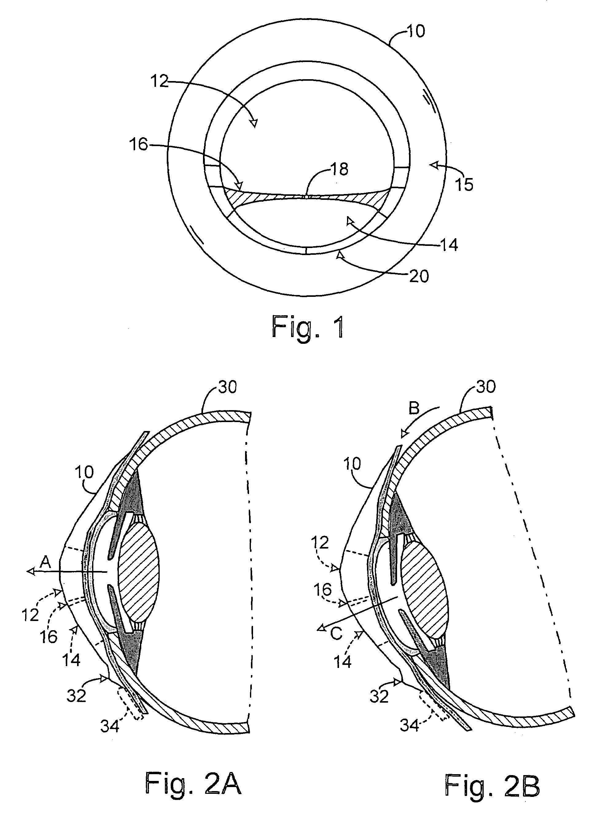
[0008]The present invention is an ophthalmic lens, such as bifocal contact lens, which is worn on the anterior surface of the cornea and has a blended design for a segmented bifocal or multifocal optical zone. The lens has an anterior surface and an opposite posterior surface, wherein the anterior surface includes a vertical meridian, a horizontal meridian, a central optical zone having at least a first optical zone for primary gaze, a second optical zone for down-gaze and an optical blending zone between the first and second optical zones. The optical blending zone has a surface that ensures a smooth surface transition from the first optical zone to the second optical zone and that allows the first and second optical zone to be designed independently and optimally so that ghost images or blur from the transition between the first and second optical zones can be minimized or eliminated. In a preferred embodiment, the optical blending zone preferably has mirror symmetry with respect to a plane cutting through the vertical meridian, outwardly flares from the vertical meridian towards the periphery of the contact lens 10. The width of the blend zone 16 increases toward the periphery of the optical zones to provide controlled curvature, controlled optical power, and a smooth surface transition to the optical zone-to-lenticular zone blend. The optical blend zone can also include a curvature magnitude to refract light away from the macular region of the eye.
[0009]The invention also includes a method of manufacturing an ophthalmic lens worn on the anterior surface of the cornea and having a blended design for a segmented optical zone through the steps of designing the anterior surface and the posterior surface the ophthalmic lens, wherein the anterior includes a vertical meridian, a horizontal meridian, a central optical zone having at least a first optical zone for primary gaze, a second optical zone for down-gaze and an optical blending zone between the first and second optical zones. The optical blending zone has a surface that ensures a smooth surface transition from the first optical zone to the second optical zone and that allows the first and second optical zone to be designed independently and optimally so that ghost images or blur from the transition between the first and second optical zones can be minimized or eliminated. In a preferred embodiment, the optical blending zone preferably has mirror symmetry with respect to a plane cutting through the vertical meridian, outwardly flares from the vertical meridian towards the periphery of the contact lens 10. The width of the blend zone 16 increases toward the periphery of the optical zones to provide controlled curvature, controlled optical power, and a smooth surface transition to the optical zone-to-lenticular zone blend. The optical blend zone can also include a curvature magnitude to refract light away from the macular region of the eye.
[0010]The present invention accordingly provides an ophthalmic lens that has a smooth surface blend zone between the optical segments. The blend zone of the lens includes a curvature of a magnitude such that it completely refracts the light away from the Macular region of the eye, of the wearer, to further minimize the appearance of ghost images or image blur.

Problems solved by technology

Ghost images are caused when the images from multiple optical zones have lateral separation.
Additionally, the blend zone between the upper and lower optical zones can create a variable power optical zone with lateral image separation that likewise causes ghost images to the wearer.

Method used


Image

  • Ophthalmic lens having an optical zone blend design
  • Ophthalmic lens having an optical zone blend design
  • Ophthalmic lens having an optical zone blend design

Examples


Embodiment Construction

[0016]With reference to the figures in which like numerals represent like elements throughout, FIG. 1 illustrates a bifocal contact lens 10 worn on the anterior surface of the cornea, of the eye 30 (FIGS. 2A and 2B), according to a preferred embodiment. In accordance with this preferred embodiment of the invention, the bifocal contact lens 10 has an anterior surface (or front curve) and an opposite posterior surface (or base curve) which is rest on the cornea of the eye when worn by a user. The anterior surface includes a vertical meridian, a horizontal meridian, a central optical zone, a peripheral blending zone 20 extending outwardly from the central optical zone, and a peripheral (e.g., lenticular zone) 15 surrounding the blending zone.

[0017]“A lenticular” refers to a peripheral non-optical surface zone on the anterior surface of a contact lens between the optical zone and the edge. The primary function of the lenticular is to control the thickness of the lens edge and / or lens po...


PUM


Abstract

An ophthalmic lens, such as multifocal contact lens, that is worn on the surface of the eye and has a blended design for a segmented optical zone. The lens has an anterior surface and an opposite posterior surface, wherein the anterior surface includes a vertical meridian, a horizontal meridian, a central optical zone having at least a first optical zone for primary gaze, a second optical zone for down-gaze and an optical blending zone between the first and second optical zones. The optical blending zone has a surface that ensures a smooth surface transition from the first optical zone to the second optical zone and that allows the first and second optical zone to be designed independently and optimally so that ghost images or blur from the transition between the first and second optical zones can be minimized or eliminated. Image blur from the blend zone that subtends the pupil is minimized by the magnitude of the curvature of the blend zone. The optical zones will have the optimal aberration parameters to control vision.

Description

[0001]This application claims the benefit under 35 U.S.C. § 119 (e) of United States provisional application No. 60 / 446,658 filed Feb. 11, 2003, incorporated by reference in its entirety.BACKGROUND OF THE INVENTION[0002]1. Field of the Invention[0003]The present invention generally relates to ophthalmic lenses. More particularly, the invention relates to a multifocal contact lens that includes a blended design for a segmented optical zone.[0004]2. Description of the Related Art[0005]Contact lenses are ophthalmic lenses worn on the anterior cornea that are widely used for correcting many different types of vision deficiencies. These include defects such as near-sightedness (myopia) and far-sightedness (hypermetropia), astigmatism, and defects in near range vision usually associated with aging (Presbyopia). A typical single vision contact lens has a real or virtual focus, which is the point at which parallel rays of light focus when the lens is placed perpendicular to the parallel ray...

Claims


Application Information

Patent Timeline
IPC IPC(8): G02C7/06G02C7/04
CPCG02C7/043G02C7/045G02C7/048
Inventor LINDACHER, JOSEPH MICHAEL
Owner ALCON INC
Learn More