Discontinuous shielding tape for data communications cable

a technology of data communication cable and shielding tape, which is applied in the direction of cables, cables with twisted pairs/quads, cables, etc., can solve the problems of increasing the overall cable cost, interfering or crosstalk, and increasing the installation cost of shielded cables, so as to reduce the amount of reflected wave interference and maximize the variation in segments

Active Publication Date: 2017-09-19
BERK TEK
View PDF6 Cites 3 Cited by
  • Summary
  • Abstract
  • Description
  • Claims
  • Application Information

AI Technical Summary

Benefits of technology

[0015]The present arrangement overcomes the drawbacks of the prior art by providing a discontinuous shielding tape, where the conductive shielding elements, disposed on the tape substrate do not form a complete electrical connection from one end of the cable to the other. Moreover, the metal shielding elements have discontinuous spacing arrangements that not only divide the segments longitudinally (along the length of the tape) as with prior art discontinuous shielding tapes but also have the segments simultaneously divided horizontally (across the width of the tape) creating an arrangement with very little or no overlapping / repeating patterns along the length of the tape further reducing or eliminating reflected waves or interference generated therefrom.
[0018]Such an arrangement maximizes the variation in the segments not only as vertical breaks located along the longitudinal length of the shield tape, but also with horizontal breaks along the entire length of the tape. These varied segment sizes and locations, based on such breaks greatly reduce the amount of reflected wave interference generated by the discontinuous shielding tape.

Problems solved by technology

For example, in a typical installation, many LAN cables may be arranged next to one another, and signals in the pairs from a first cable may cause interference or crosstalk with another pair in an adjacent LAN cable.
This is a time consuming step that increases the cost to install the shielded cable.
One typical example requires a drain wire to be helically coiled around the shield which also increases the overall cable cost.
However, in doing so, this design has generated yet another drawback, particularly with respect to the signal quality within the pairs of the cable, owing to interference caused by signals generated by the discontinuous shield elements.
For example, with discontinuous shields, the signals traveling in the pairs can cause induced signals in discontinuous foil elements with the breaks in the shielding giving rise to reflected waves which can create issues with return loss.
Although these various arrangements may have some mitigating effect to reduce the amplitude of the reflected waves by increasing the range of frequencies that these reflections occur at, they are still not an optimum solution.

Method used


Image

  • Discontinuous shielding tape for data communications cable
  • Discontinuous shielding tape for data communications cable
  • Discontinuous shielding tape for data communications cable

Examples


Embodiment Construction

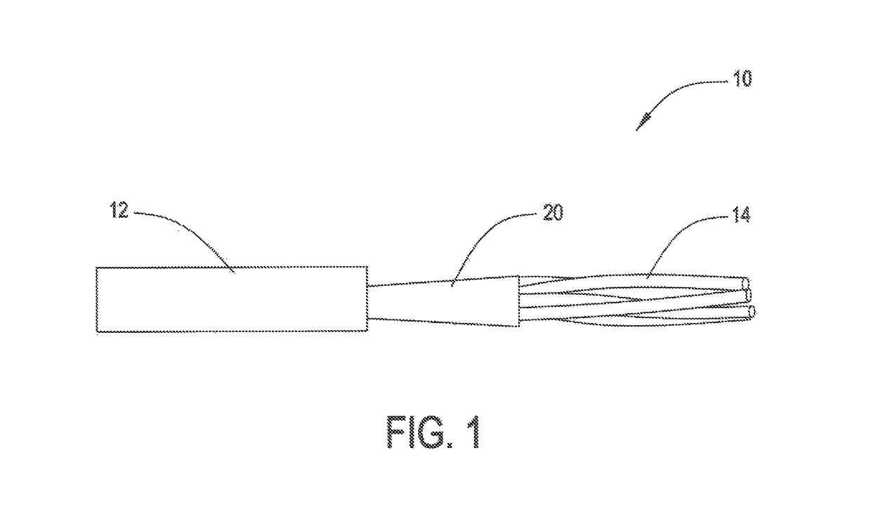
[0023]In one embodiment, FIG. 1 shows an exemplary LAN cable 10 having a jacket 12, a plurality of twisted pairs 14 and a discontinuous shield 20, disposed over pairs 14 within jacket 12. For the purpose of illustrating the salient features of the present arrangement, different versions of discontinuous shielding tape 20, shown in FIGS. 2-3, are envisioned as being applied as shown by element 20 in FIG. 1. However, it is understood that the subsequently described discontinuous shields 20, shown in FIGS. 2-3 may be equally applied to larger or smaller pair count cables, or in other communication cable designs that employ a shield.

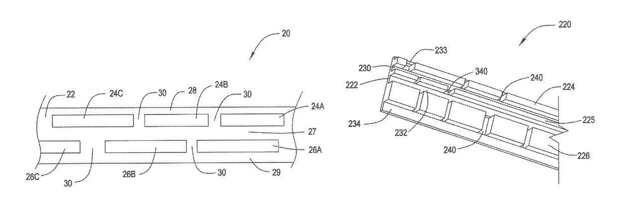
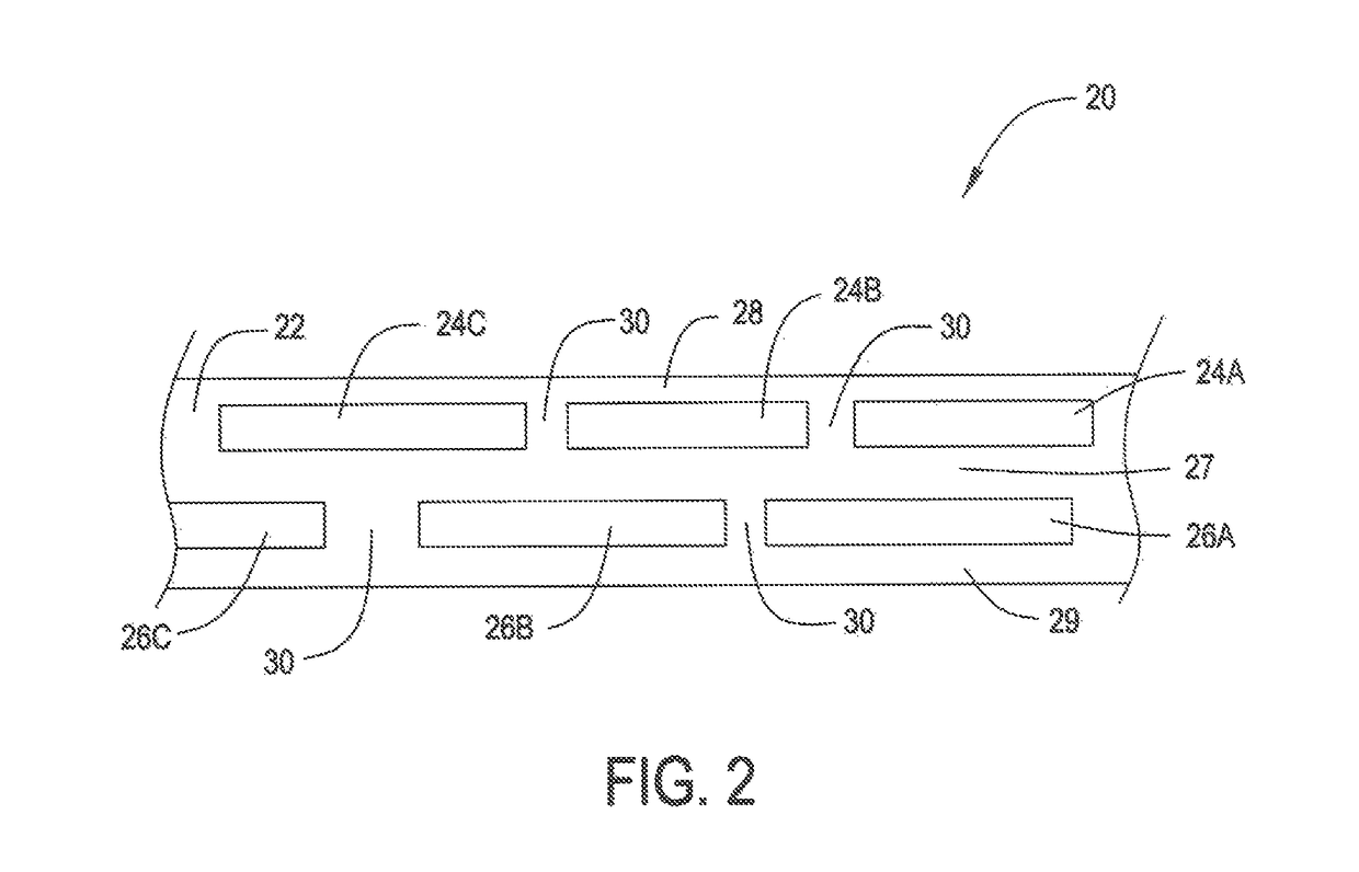
[0024]Turning to the discontinuous shielding tape 20, FIG. 2, shows a first discontinuous shielding tape 20 constructed of a first substrate 22 and at least two longitudinally running shielding elements 24 and 26.

[0025]In a preferred embodiment substrate 22 is typically a thin plastic film composed of any one of polyethylene terephthalate (Mylar™) polypropyl...


PUM

PropertyMeasurementUnit
widthaaaaaaaaaa
lengthaaaaaaaaaa
longitudinal widthsaaaaaaaaaa

Abstract

A communication cable has a plurality of twisted pair communication elements, a jacket surrounding the twisted pairs and a shield element disposed between the pairs and the jacket. The shield element is constructed as a tape substrate with a plurality of foil shielding elements disposed thereon, the foil shielding elements are formed as at least two longitudinally running strips separated by a horizontal gap. Each of the two longitudinally running strips are further separated periodically with vertical gaps disposed at varied locations with respect to the adjacent longitudinally running strip.

Description

BACKGROUND[0001]Field of the Invention[0002]This application relates to a shielding tape. More particularly, this application relates to a shielding tape for LAN (Local Area Network) cables.[0003]Description of the Related Art[0004]LAN or network type communication cables are typically constructed of a plurality of twisted pairs (two twisted conductors), enclosed within a jacket. A typical construction is to have four twisted pairs inside of a jacket, but many other larger pair count cables are available.[0005]Care is taken to construct these cables in a manner to prevent cross talk with adjacent cables. For example, in a typical installation, many LAN cables may be arranged next to one another, and signals in the pairs from a first cable may cause interference or crosstalk with another pair in an adjacent LAN cable. In order to prevent this, the lay length or twist rates of the pairs in a cable are varied differently from one another. Additionally, when pairs in adjacent cables are...

Claims


Application Information

Patent Timeline
Patent Type & Authority Patents(United States)
IPC IPC(8): H01B11/06H01B11/10
CPCH01B11/1008
Inventor HESS, BRADLEYKOPP, MITCHABERASTURI, THOMAS
Owner BERK TEK
Why Eureka
Try Eureka