
Authentication by use of symmetric and asymmetric cryptography

a cryptography and symmetric algorithm technology, applied in the field of authentication methods, can solve the problems of prohibitive constraints, asymmetric algorithms are usually slow, and hardware implementations are significantly more resource-intensive, and achieve the effect of fast and reliable authentication of communication devices

Active Publication Date: 2017-09-26
EM MICROELECTRONIC-MARIN
View PDF23 Cites 0 Cited by
  • Summary
  • Abstract
  • Description
  • Claims
  • Application Information

AI Technical Summary

Benefits of technology

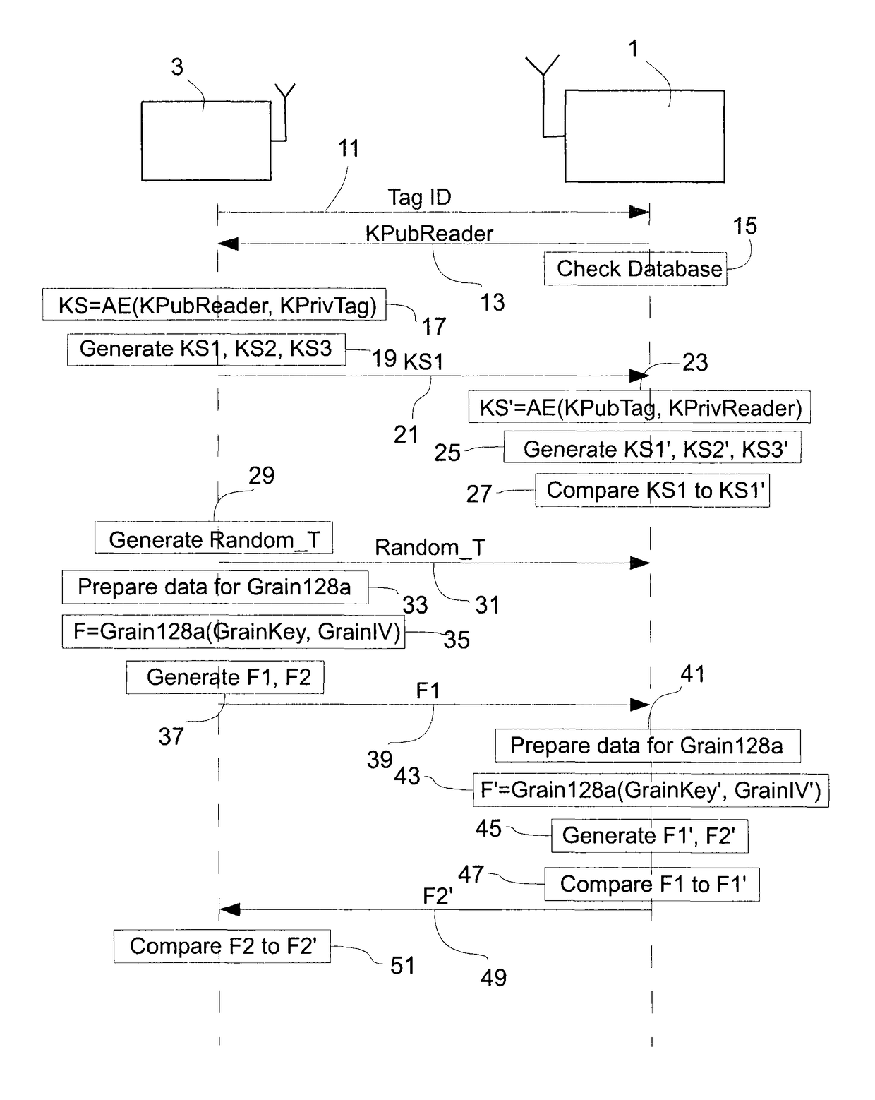
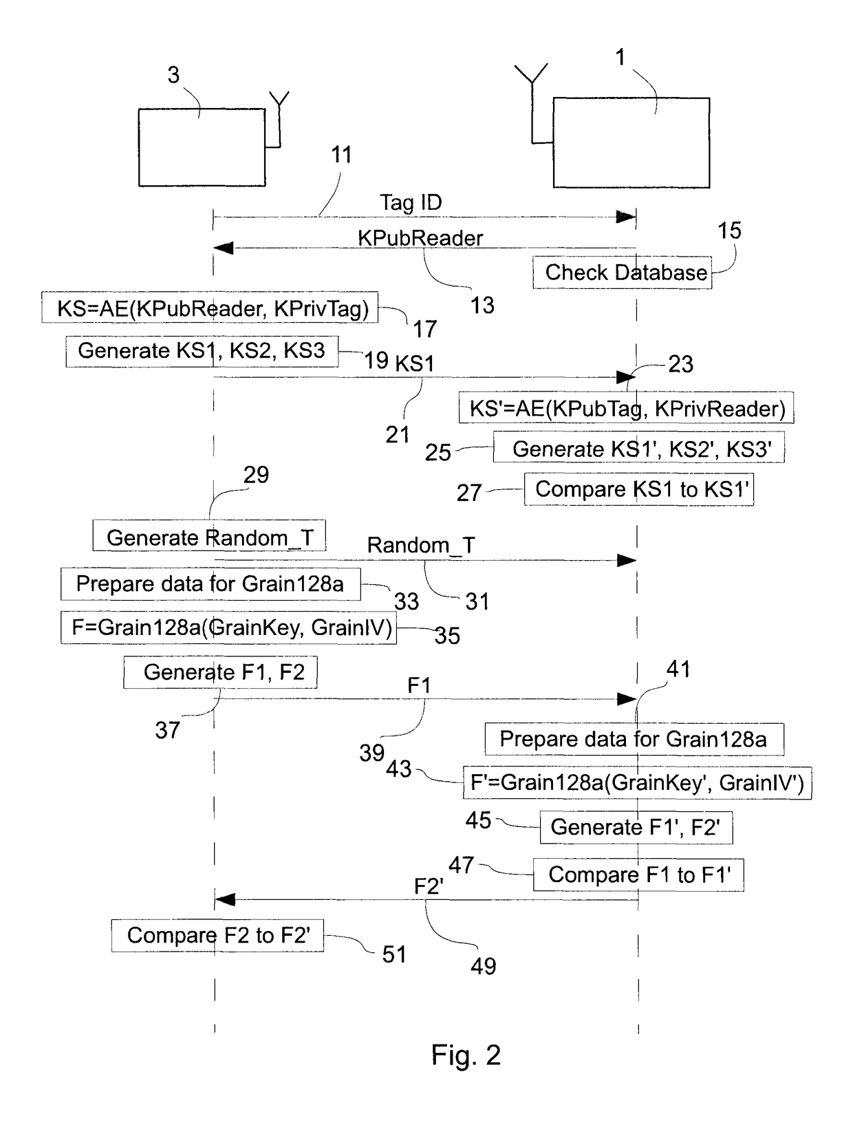
[0017]The proposed new solution has the advantage that the second communication device can be authenticated quickly and reliably and that the second session key of the first communication device for the mutual authentication is obtained with minimal processing power. This means for instance that the first communication device does not need to generate a random number, unlike standard symmetric algorithms, because the first session key of the first communication device is used to generate the second session key of the first communication device. Thus, when the symmetric algorithm of the invention is used, only the steps necessary to authenticate the first communication device are needed. Accordingly, the present invention provides a smart combination of asymmetric and symmetric authentication protocols.

Problems solved by technology

In open systems, key management is more critical and may indeed represent a prohibitive constraint.
Asymmetric algorithms are usually slow compared with symmetric algorithms, and the hardware implementations are significantly more resource-intensive.
Additionally, the application may have requirements for very fast transaction times (e.g. <20 ms) which further restrict possible solutions.
Assume a tag from Agency A is read by a reader from Agency B. TA is only possible if Agency A is willing to share the tag's key with Agency B. For symmetric cryptography, Agency A must provide the tag's secret key to Agency B. Key exchange between agencies can be difficult and represents a finite risk of compromising all the tag secret keys.
This risk is often great enough to affect communication adversely between the parties.
The problem is thus related to the speed of the transaction.
One of the bottlenecks is the time taken to select the appropriate authentication protocol.

Method used


Image

  • Authentication by use of symmetric and asymmetric cryptography
  • Authentication by use of symmetric and asymmetric cryptography
  • Authentication by use of symmetric and asymmetric cryptography

Examples


Embodiment Construction

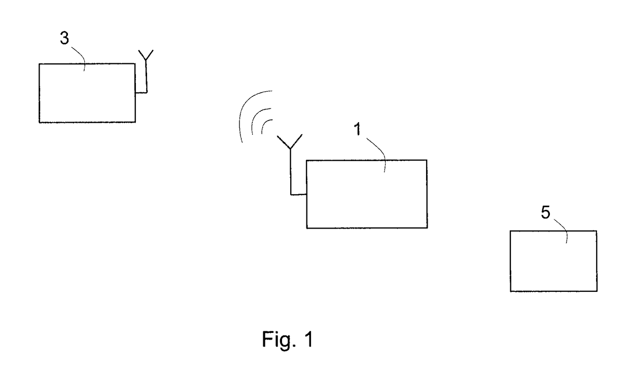
[0037]An embodiment of the present invention will now be described in detail with reference to the attached figures. This embodiment will be described in the context of an RFID system used for road toll collection. However, the teachings of the present invention are not limited to the field of RFID or to toll collection applications. Identical functional and structural elements which appear in the different drawings are assigned the same reference numerals.

[0038]FIG. 1 shows an RFID system to which the teachings of the present invention can be applied. A first communication device 1, which may be an RFID reader or interrogator, is arranged to communicate with a second communication device 3, which may be an RFID tag, by means of radio frequency electromagnetic fields. The tag 3 contains electronically stored information. The tag 3 may be powered and read by the reader 1 at short ranges (for example a few meters) via magnetic fields (electromagnetic induction), and then act as a pass...


PUM


Abstract

The present invention concerns a mutual authentication method in a communication system. According to the method, a first communication device (1), such as an RFID reader, authenticates a second communication device (3), such as an RFID tag, by using an asymmetric authentication protocol based on a generated a session key. The tag authenticates the reader by using a symmetric communication protocol based on a generated other session key. At least a portion of the session key is used to generate the other session key.

Description

TECHNICAL FIELD[0001]The invention relates to the field of authentication methods. For instance, the teachings of the present invention can be applied in radio frequency identification (RFID) systems. The invention also relates to communication devices involved in the authentication method and to a communication system where the teachings of the present invention can be applied.BACKGROUND OF THE INVENTION[0002]In many communication systems, such as RFID systems, it is important to be able to authenticate different parties of the communication system. For instance, RFID systems that are used for many applications consist of one or more RFID readers, also known as interrogators or base stations, and one or more RFID tags, also known as labels or transponders. Some applications (e.g. tolling) benefit from having functionality to determine if tags and their data content are genuine or counterfeit. A common approach for this functionality is to utilize cryptographic methods to perform ta...

Claims


Application Information

Patent Timeline
Patent Type & Authority Patents(United States)
IPC IPC(8): H04L29/06H04L9/32G06F7/58H04L9/08
CPCH04L63/061G06F7/588H04L9/0844H04L9/3273H04L63/0435H04L63/0442H04L2209/805H04L2209/84
Inventor SPRINGER, JAMES J.SALGADO, STEPHANIE
Owner EM MICROELECTRONIC-MARIN
Learn More