Eyewear for automatically detecting and blocking sources of glare

a technology of automatic detection and blocking of glare sources, applied in the field of eyewear, can solve the problems of reduced visibility, driver may suffer significant visual disability, and standard sunglasses cannot account for specific glare sources

Active Publication Date: 2018-10-04
RGT UNIV OF MICHIGAN
View PDF2 Cites 0 Cited by
  • Summary
  • Abstract
  • Description
  • Claims
  • Application Information

AI Technical Summary

Benefits of technology

[0005]Unfortunately, standard sunglasses cannot account for specific glare sources and can have a contributory effect in reducing visibility to ancillary areas, such as to the side of the light source. Often times, a user must shift their view, position, or employ obstruction devices (e.g. sunshade) to counteract these effects.
[0017]According to the principles of the present teachings, in some embodiments, the prototype system utilizes a smart phone display and camera. The light source for the display would need to be stripped off the back of the display. Removing the light source should dramatically reduce power demand, which would aid in making a device with low enough weight to be wearable. Processing power requirements also appear to be minimal, but might require scavenging a separate chip from some other source.
[0019]It darkens a small circle (2.5 to 3 mm) to block out the glare source while preserving overall vision. In some embodiments, this is done by mounting a micro camera directly on a pair of eyeglasses, goggles, or other eyewear and also by replacing any lenses with a transparent LCD panel.
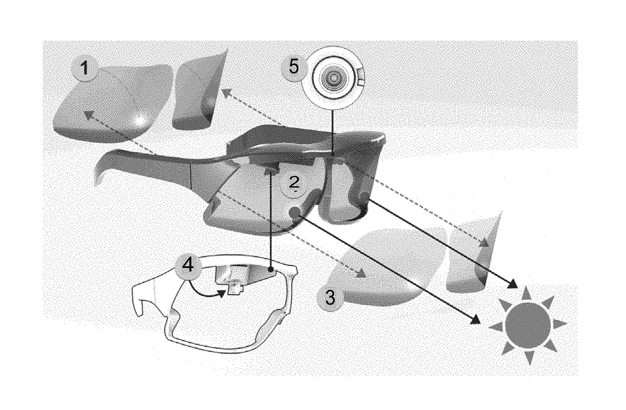
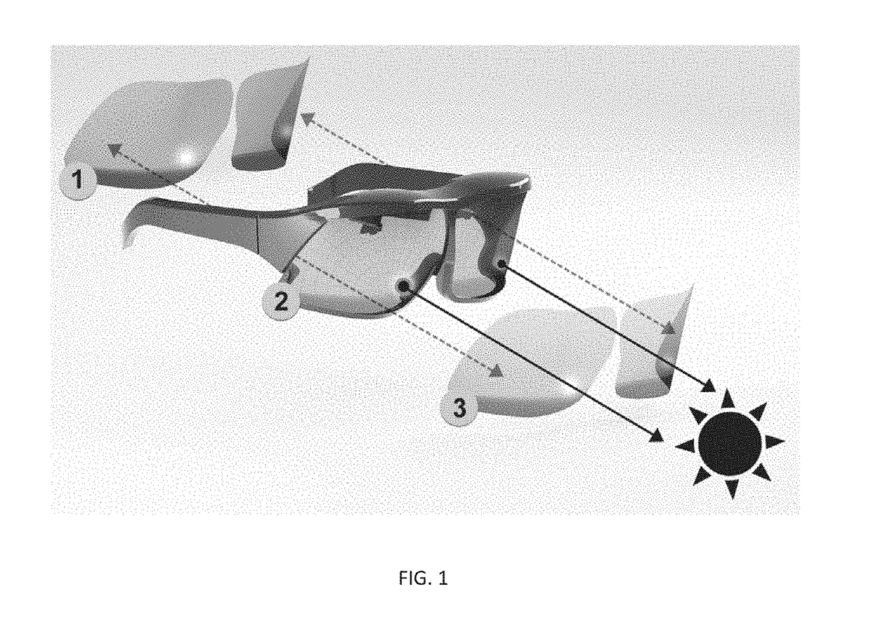
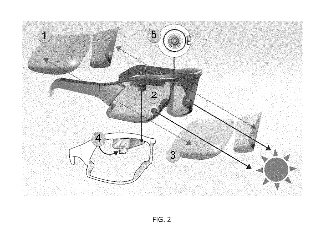
[0022]As illustrated in FIG. 1, in some embodiments, a first transparent LCD 1, a second transparent LCD 2 with circle of pixels centered on the line of sight to block the glare source, and a transparent glass 3 with the view of glare source in line of sight are provided. In this embodiment, two LCD panel lenses are needed. A minimum 3 mm circle is still required to block the glare source, but in this case the circle is created by the overlap of two patterns on the two lenses. The patterns can be a simple set of stripes on each lens. Also changing the relative phase of the two arrays of stripes changes the angles which light can and cannot pass through the two arrays. This means that the 3 mm circle can partially overlap the line of sight, yet still allow a view along the line of sight, while blocking the view of the glare source.

Problems solved by technology

It is well known that sources of intense light can result in reduced visibility.
In such situations, a driver may suffer significant visual disability.
However, this can also occur from any other intense source of light, such artificial lights, reflections, and the like.
Unfortunately, standard sunglasses cannot account for specific glare sources and can have a contributory effect in reducing visibility to ancillary areas, such as to the side of the light source.

Method used


Image

  • Eyewear for automatically detecting and blocking sources of glare
  • Eyewear for automatically detecting and blocking sources of glare
  • Eyewear for automatically detecting and blocking sources of glare

Examples


Embodiment Construction

[0012]Example embodiments will now be described more fully with reference to the accompanying drawings. Example embodiments are provided so that this disclosure will be thorough, and will fully convey the scope to those who are skilled in the art. Numerous specific details are set forth such as examples of specific components, devices, and methods, to provide a thorough understanding of embodiments of the present disclosure. It will be apparent to those skilled in the art that specific details need not be employed, that example embodiments may be embodied in many different forms and that neither should be construed to limit the scope of the disclosure. In some example embodiments, well-known processes, well-known device structures, and well-known technologies are not described in detail.

[0013]The terminology used herein is for the purpose of describing particular example embodiments only and is not intended to be limiting. As used herein, the singular forms “a,”“an,” and “the” may b...


PUM

PropertyMeasurementUnit
pixel sizeaaaaaaaaaa
angular widthaaaaaaaaaa
widthaaaaaaaaaa

Abstract

An eyewear system for automatically detecting and blocking a source of glare from at least one eye of a user. The eyewear system having a first transparent LCD lens; a second transparent LCD lens having a plurality of pixel positions, each of the plurality of pixel positions configured to activate to block the source of glare from the eye of the user; a transparent material with a view of the source of glare; and a control system for detecting the source of the glare and activating at least one of the plurality of pixel positions.

Description

CROSS-REFERENCE TO RELATED APPLICATIONS[0001]This application claims the benefit of U.S. Provisional Application No. 62 / 480,579, filed Apr. 3, 2017. The entire disclosure of the above application is incorporated herein by reference.FIELD[0002]The present disclosure relates to eyewear and, more particularly, relates to eyewear that automatically detects and blocks sources of glare.BACKGROUND AND SUMMARY[0003]This section provides background information related to the present disclosure which is not necessarily prior art. This section provides a general summary of the disclosure, and is not a comprehensive disclosure of its full scope or all of its features.[0004]It is well known that sources of intense light can result in reduced visibility. This can particularly occur while driving in an easterly or westerly direction during sunrise or sunset. In such situations, a driver may suffer significant visual disability. However, this can also occur from any other intense source of light, s...

Claims


Application Information

Patent Timeline
Patent Type & Authority Applications(United States)
IPC IPC(8): G02C7/10G02F1/133
CPCG02C7/101G02F1/13318G02F2001/13312G02C7/105G02F1/13471G02F1/13312
Inventor NAVVAB, MOJTABA
Owner RGT UNIV OF MICHIGAN
Why Eureka
Try Eureka