Method and system for static and dynamic positioning or controlling motion of marine structure

a technology of static and dynamic positioning and motion control, which is applied in the direction of instruments, borehole/well accessories, force measurement by measuring optical property variation, etc., can solve the problems of limited use of concrete structures, easy corrosion of steel products, and hardship on their operation, so as to reduce the cost of underwater inspection and extend the life. , the effect of accurately figuring ou

Active Publication Date: 2017-10-03
CYTRONIQ
View PDF18 Cites 2 Cited by
  • Summary
  • Abstract
  • Description
  • Claims
  • Application Information

AI Technical Summary

Benefits of technology

[0095]According to the present disclosure, it is possible to measure a tension of a mooring line by means of real-time monitoring of the mooring line and suitably perform static and dynamic positioning or motion control and management to the marine structure automatically based thereon. In addition, by accurately expecting a life of the mooring line by means of static and dynamic real-time monitoring of the mooring line, it is possible to extend the life by avoiding a critical point of the mooring line. Moreover, even though a lot of costs are consumed to perform periodic underwater ROV inspection to a mooring line, in the present disclosure, the cost required for the underwater inspection may be reduced since the mooring line is monitored in real time. Further, since at least one sensor is applied to the mooring line, a mode shape of the mooring line may be accurately figured out, and also it is possible to obtain a direction and velocity of sea current and tide per season, per day or according to each water depth.

Problems solved by technology

Steel products are easily corroded and sessile marine lives easily inhabit thereat.
However, such a concrete structure is limitedly used in the North Sea or polar regions since it is not easily fabricated and also limited to seabed topography conditions.
A drill ship has a self-propulsive function to ensure mobility, but its fixedness is ensured by means of mooring or dynamic positioning, which causes rolling or pitching under a bad weather to cause hardship on its operation.
The jack-up rig ensures better fixedness in comparison to a drill ship, but it cannot operate at a deep area and does not ensure good mobility.
In addition, under a bad weather, the jack-up operation may be temporarily interrupted.
The semisubmersible oil drilling ship is structurally stable but may come into an unstable state at a bad weather since it has a great upper deck area and is likely to contain a lot of equipment thereon.
The semisubmersible oil drilling ship also requires great fabrication and operation costs since it does not have a self-propulsive function.
Recently, it is attempted to build nuclear power plants, gas turbines, wave power plants, tidal power plants, see breeze power plants, solar power plants, waste incinerators or the like on a floating structure on the sea since it becomes more difficult to choose a site therefor due to environmental pollution and NIMBY phenomenon.
If any unusual structure in a fault or sedimentary stratum, an abrupt change of the seabed topography, abnormal erosion, a stream of sediments or the like is found in the seas around the structure, a serious problem may occur on the stability of the structure.
However, ascending and descending of the sea level is not caused only by celestial bodies, but the phenomenon locally caused by wind, wave, or difference in pressures should not be ignored.
Therefore, if this effect is not suitably considered in designing, a serious problem may be caused.
In addition, the external surface of each component becomes rougher to increase a drag effect, and in case of a steel material, corrosion may be locally promoted.
Meanwhile, as sessile marine lives cover the surface of the structure, it becomes more difficult to maintain and manage the marine structure, and thus it is required to partially remove the marine bodies.
The fixed structure needs a small maintenance cost and has a high operation rate in the oil unloading work, while the single-point mooring system needs more maintenance cost but has a low early stage investment.
Mooring using a mooring cable is limited to a water level, and thus there are not many records in a water level over several hundred meters even for an oil drilling rig.
In particular, in a marine structure having a riser, the ratio has a limit of about 5%, and if the ratio becomes 10%, the riser may be bent or broken.
Here, if the mooring line and the anchor are broken beyond an allowable level of the system, a flexible riser connecting the single point mooring (SPM) and the pipe line end manifold (PLEM) is damaged, which results in spillage of high-pressure and high-temperature crude oil.
Such an oil spillage accident causes huge economical, life and environmental losses.
In fact, a mooring device is not designed suitably for an environment of an installation region, and an interpretation program for mooring devices is imported from foreign countries, which consumes enormous foreign currency.
In addition, a tension applied to each mooring line of a marine structure is not regular but changes continuously due to a loading amount, a change of tide, or a difference between the ebb and flow.

Method used


Image

  • Method and system for static and dynamic positioning or controlling motion of marine structure
  • Method and system for static and dynamic positioning or controlling motion of marine structure
  • Method and system for static and dynamic positioning or controlling motion of marine structure

Examples


Embodiment Construction

[0120]Hereinafter, the present disclosure will be described in detail with reference to the accompanying drawings. First, when endowing reference symbols to components in each figure, it should be understood that the same component is designated by the same reference symbol though it is depicted in several figures. In addition, in the explanation of the present disclosure, if any known component or function is deemed to make the essence of the present disclosure unclear, this may not be described in detail.

[0121]System for Static and Dynamic Positioning or Motion Control of a Marine Structure by Using Real-Time Monitoring of at Least One of a Mooring Line, Marine Environments, 6-Dof Movement of a Marine Structure, a Tank State, a Ship Topside, the Seabed, or their Combinations

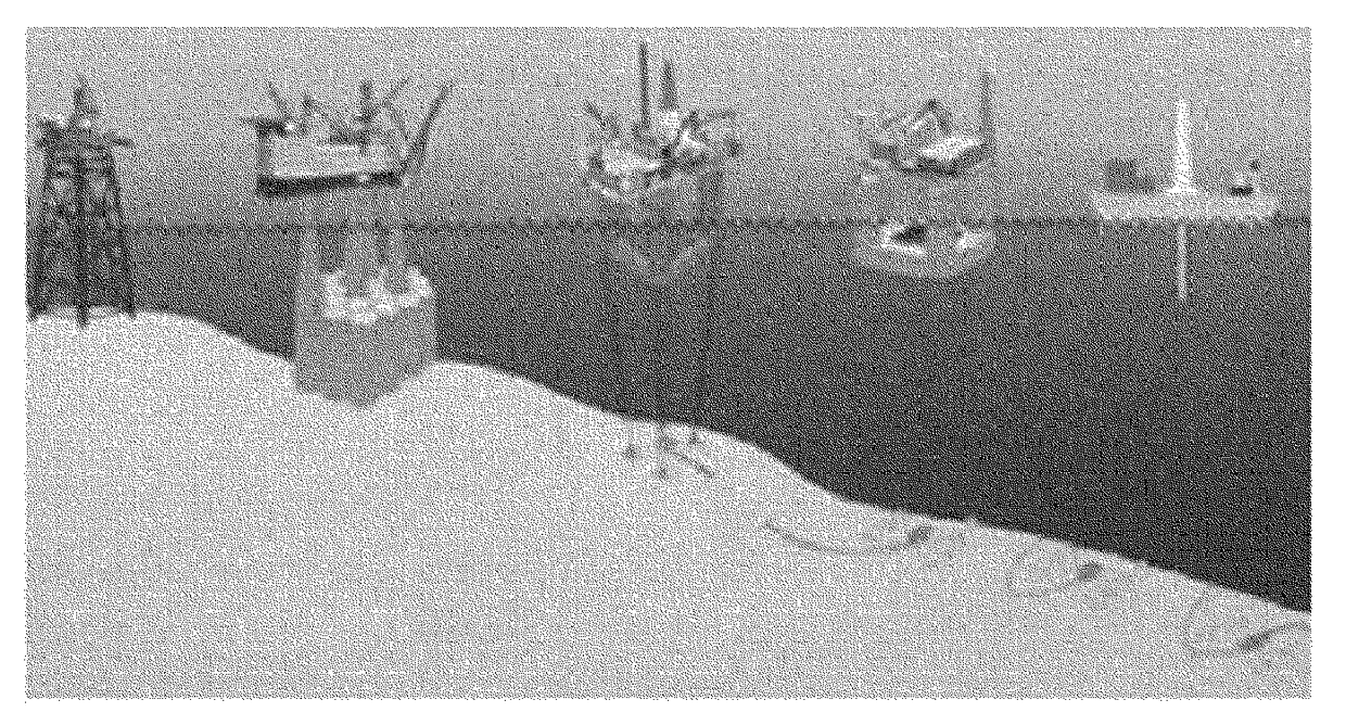
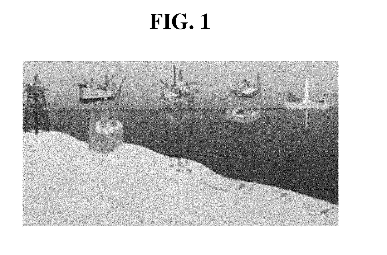
[0122]FIG. 10 is a diagram showing surrounding environments of a marine structure to which the present disclosure is applied, FIGS. 11A to 11F are block diagrams showing a system for static and dynamic position...


PUM

PropertyMeasurementUnit
depthaaaaaaaaaa
thicknessaaaaaaaaaa
degrees of freedomaaaaaaaaaa

Abstract

Disclosed is a system and method for static and dynamic positioning or motion control of a marine structure by using real-time monitoring of at least one of a mooring line, marine environments, 6-dof movement of a marine structure, a tank state, a ship topside, the seabed, or their combinations. The static and dynamic real-time monitoring data of the mooring line is obtained and processed for positioning the marine structure or controlling and managing a motion thereof. Here, 1) a tension of a mooring line is measured by means of real-time monitoring of the mooring line, 2) various marine environment elements such as wind direction, wind speed, air humidity, atmospheric pressure, atmosphere temperature, cloud height, visibility, ocean wave, wave height, sea current speed, sea current direction, rain or the like are measured by means of real-time monitoring of the marine environments, 3) 6-dof movement of the marine structure is measured by means of real-time monitoring of the marine structure, 4) ullage and sloshing data of various tanks in the marine structure are measured by means of real-time monitoring of tank states, 5) damage and life of pipes, facilities or the like located at a ship topside of the marine structure are measured by means of real-time monitoring of the ship topside, 6) damage and life of umbilical cables, pipes, pumps and valves located on the seabed are measured by means of real-time monitoring of the seabed, and suitable static and dynamic positioning or motion control and management may be automatically performed based thereon.

Description

CROSS-REFERENCE TO RELATED APPLICATIONS[0001]This is a continuation of International Application No. PCT / KR2013 / 002972 filed on Apr. 9, 2013, which claims priority to Korean Application Nos. 10-2012-0036946, 10-2012-0036947, 10-2012-0036948, 10-2012-0036949, 10-2012-0036950, and 10-2012-0036951 filed on Apr. 9, 2012. The applications are incorporated herein by reference.TECHNICAL FIELD[0002]The present disclosure relates to a system and method for static and dynamic positioning or motion control of a marine structure, and more particularly, to a system and method for static and dynamic positioning or motion control of a marine structure by using real-time monitoring of a mooring line, in which environmental external forces are reflected to monitor periodic or non-periodic coupled energy and response by a hydrodynamic or aerodynamic characteristic of a marine structure and a riser and mooring line in real time and an optimal static and dynamic positioning or motion control is perform...

Claims


Application Information

Patent Timeline
Patent Type & Authority Patents(United States)
IPC IPC(8): B63B21/50B63B39/00B63H25/00G05D1/02G01L1/24B63B43/06B63B35/44E21B41/00B63B21/16
CPCB63B21/50B63B35/44B63B39/00B63B43/06B63H25/00E21B41/00G01L1/246G05D1/0208B63B21/16B63B2702/02E21B41/0007
Inventor LEE
Owner CYTRONIQ
Why Eureka
Try Eureka