Tool tray systems and devices

a tool tray and tool technology, applied in the field of tool tray systems and devices, can solve the problems of significant more difficult to grasp and manipulate small objects, increase the probability that an item will fall off the bucket lip, and lose hardware and productivity, so as to facilitate the manipulation and storage of hardware and tools

Active Publication Date: 2017-10-10
INVOKE 3D LLC
View PDF9 Cites 10 Cited by
  • Summary
  • Abstract
  • Description
  • Claims
  • Application Information

AI Technical Summary

Benefits of technology

[0008]In various embodiments, the present disclosure provides a novel tool tray apparatus having the capability of attaching to various elevated work stations including aerial buckets. The present disclosure comprises an interior tray surface bordered by four sidewalls and one or more means for attaching the device to an elevated workstation, which may comprise one or more saddles which are capable of engaging with a means for securing the device to the lip of an aerial bucket or other raised workstation. In some embodiments, the device further comprises one or more ramps capable of providing a sloped transitional surface from the base of the interior surface to the top of one or more sidewalls. In other embodiments, the device also comprises a means for storing and organizing hardware such as nuts and washers through a removable, vertically oriented dowel and stanchion. In these embodiments, the inclusion of a tray ramp, dowel, and stanchion help facilitate the manipulation and storage of hardware and tools by gloved hands.

Problems solved by technology

These thick gloves make it significantly more difficult to grasp and manipulate small objects.
Tools and hardware stored on the lip of the bucket have a high probability of falling off the lip resulting in lost hardware and productivity.
The use of gloves when manipulating tools and hardware stored on the lip of the bucket further increases the probability that an item will fall off the bucket lip.
However, when using gloves linemen can have great difficulty retrieving and manipulating specific items in the pockets of these bag storage devices.

Method used


Image

  • Tool tray systems and devices
  • Tool tray systems and devices
  • Tool tray systems and devices

Examples


Embodiment Construction

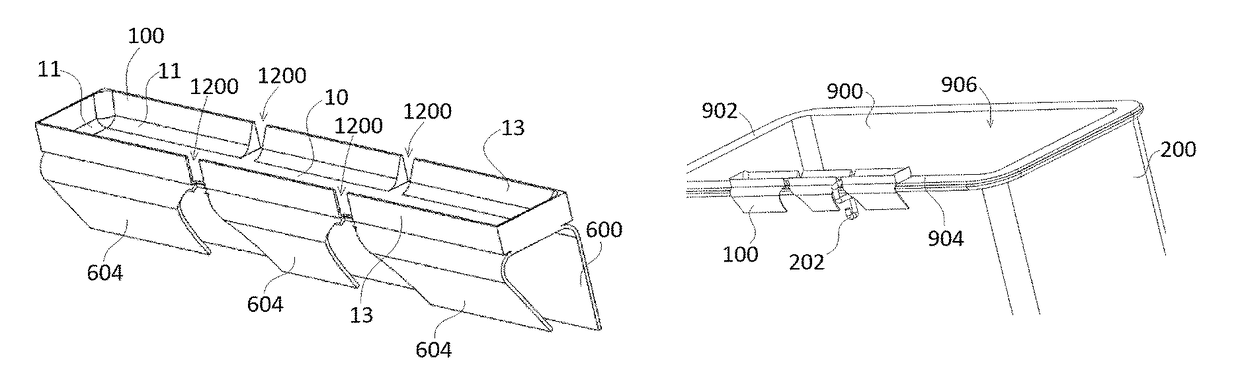
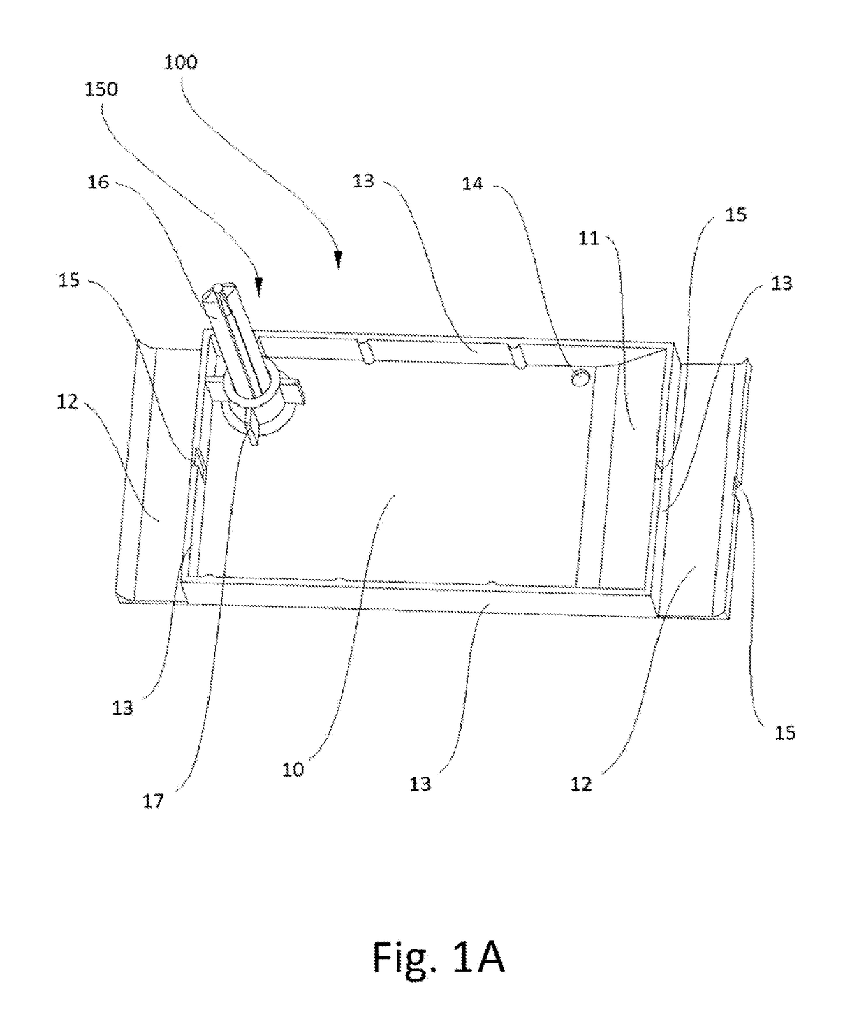
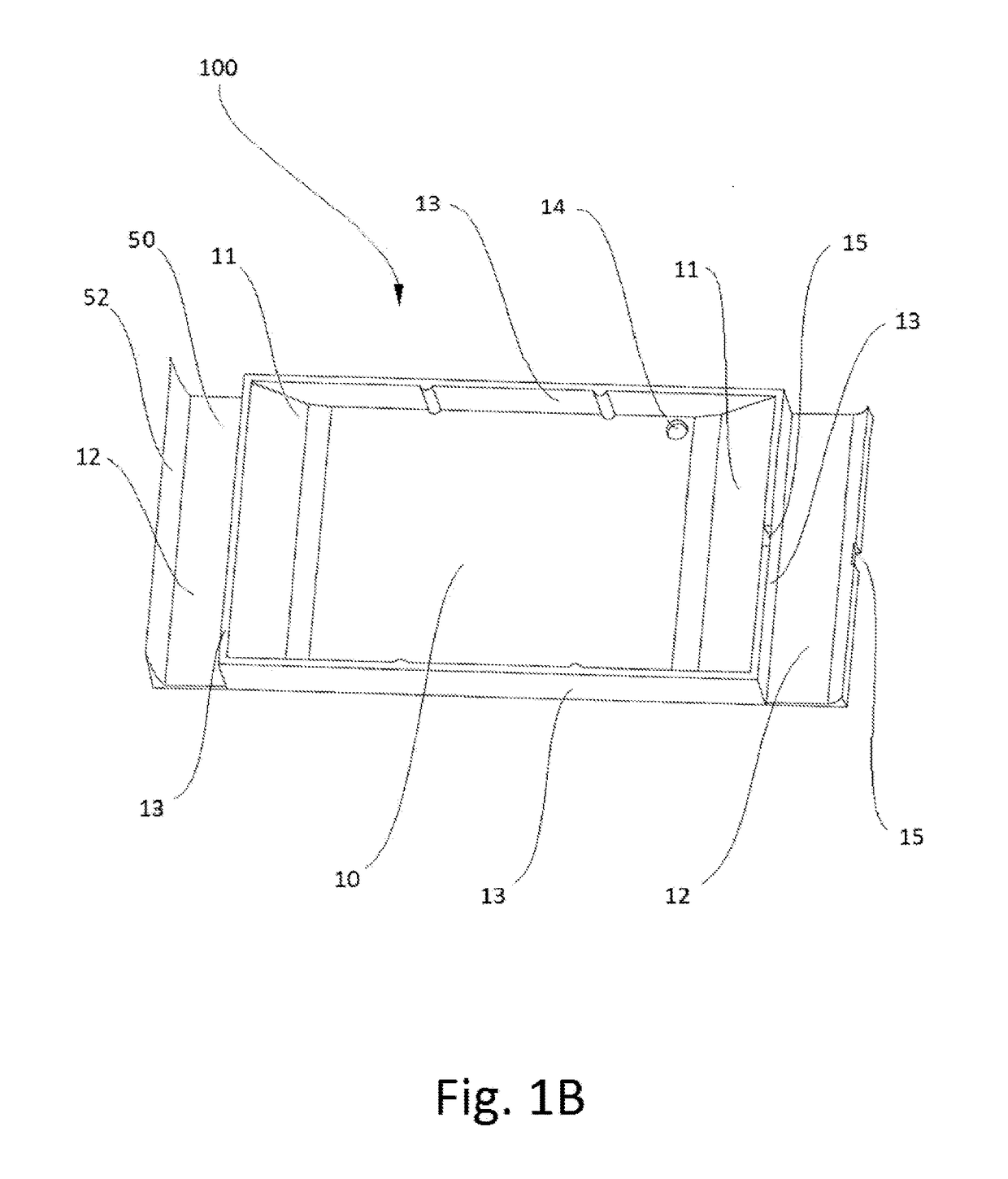
[0044]For the purposes of promoting an understanding of the principles of the present disclosure, reference will now be made to the embodiments illustrated in the drawings, and specific language will be used to describe the same. It will nevertheless be understood that no limitation of the scope of this disclosure is thereby intended.

[0045]The terminology used herein is for the purpose of describing particular embodiments only and is not intended to be limiting of the present disclosure. As used herein, the term “and / or” includes any and all combinations of one or more of the associated listed items. As used herein, the singular forms “a,”“an,” and “the” are intended to include the plural forms as well as the singular forms, unless the context clearly indicates otherwise. It will be further understood that the terms “comprises” and / or “comprising,” when used in this specification, specify the presence of stated features, steps, operations, elements, and / or components, but do not pre...


PUM


Abstract

Novel tool tray systems and devices. In at least one exemplary embodiment of a tray of the present disclosure, the tray comprises an interior tray section configured to receive one or more items, the interior tray at least partially surrounded by at least one sidewall having a height, a first ramp portion in communication with the interior tray section, the first ramp portion defining a sloping surface that extends from the interior tray section to a top of the at least one sidewall, wherein the at least one tray is configured to be secured to an inner lip of an aerial bucket liner.

Description

PRIORITY[0001]The present application a) is related to, claims the priority of, and is a continuation-in-part of, U.S. Nonprovisional patent application Ser. No. 14 / 329,937, filed Jul. 12, 2014, which is related to, and claims the priority benefit of, U.S. Provisional Patent Application Ser. No. 61 / 845,441, filed Jul. 12, 2013; b) is related to, and claims the priority benefit of, U.S. Provisional Patent Application Ser. No. 62 / 043,000, filed Aug. 28, 2014; and c) is related to, and claims the priority benefit of, U.S. Provisional Patent Application Ser. No. 62 / 115,797, filed Feb. 13, 2015. The contents of each of the aforementioned applications are hereby incorporated by reference in their entirety into the present disclosure.BACKGROUND[0002]Utility linemen are often required to work in elevated workstations such as utility trucks with aerial buckets. These aerial buckets are typically located at the end of an extendable hydraulically driven arm that is attached to a truck or other...

Claims


Application Information

Patent Timeline
Patent Type & Authority Patents(United States)
IPC IPC(8): B25H3/06
CPCB25H3/06
Inventor BLAKE, DEWAYNE EUGENE
Owner INVOKE 3D LLC
Why Eureka
Try Eureka