Compensated deep propagation measurements with differential rotation

a deep propagation and differential rotation technology, applied in the field of downhole electromagnetic logging, can solve the problems of insensitive bending and alignment angle error in disclosed methods and apparatus, complex actual formation structure, and inability to provide fully gain compensated tri-axial propagation measuremen

Inactive Publication Date: 2017-10-10
SCHLUMBERGER TECH CORP
View PDF54 Cites 5 Cited by
  • Summary
  • Abstract
  • Description
  • Claims
  • Application Information

AI Technical Summary

Benefits of technology

[0007]The disclosed embodiments may provide various technical advantages. For example, the disclosed methodology provides a method for obtaining a gain compensated three-dimensional matrix of deep electromagnetic measurements using orthogonal antennas in which a lower sensor sub rotates a different rate than an upper sensor sub. The acquired measurements are fully gain compensated and independent of antenna tilt angle variation. Moreover, the disclosed method and apparatus tends to be insensitive to bending and alignment angle errors.

Problems solved by technology

One challenge in utilizing directional electromagnetic resistivity measurements, is obtaining a sufficient quantity of data to perform a reliable inversion.
The actual formation structure is frequently significantly more complex than the formation models used in the inversion.
However, there are no known methods for providing a fully gain compensated tri-axial propagation measurement, especially in a BHA configuration in which upper and lower antenna subs rotate at different rates (e.g., as used in power drilling).
Moreover, the disclosed method and apparatus tends to be insensitive to bending and alignment angle errors.

Method used


Image

  • Compensated deep propagation measurements with differential rotation
  • Compensated deep propagation measurements with differential rotation
  • Compensated deep propagation measurements with differential rotation

Examples


embodiment 50

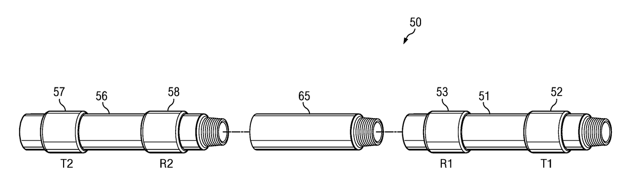
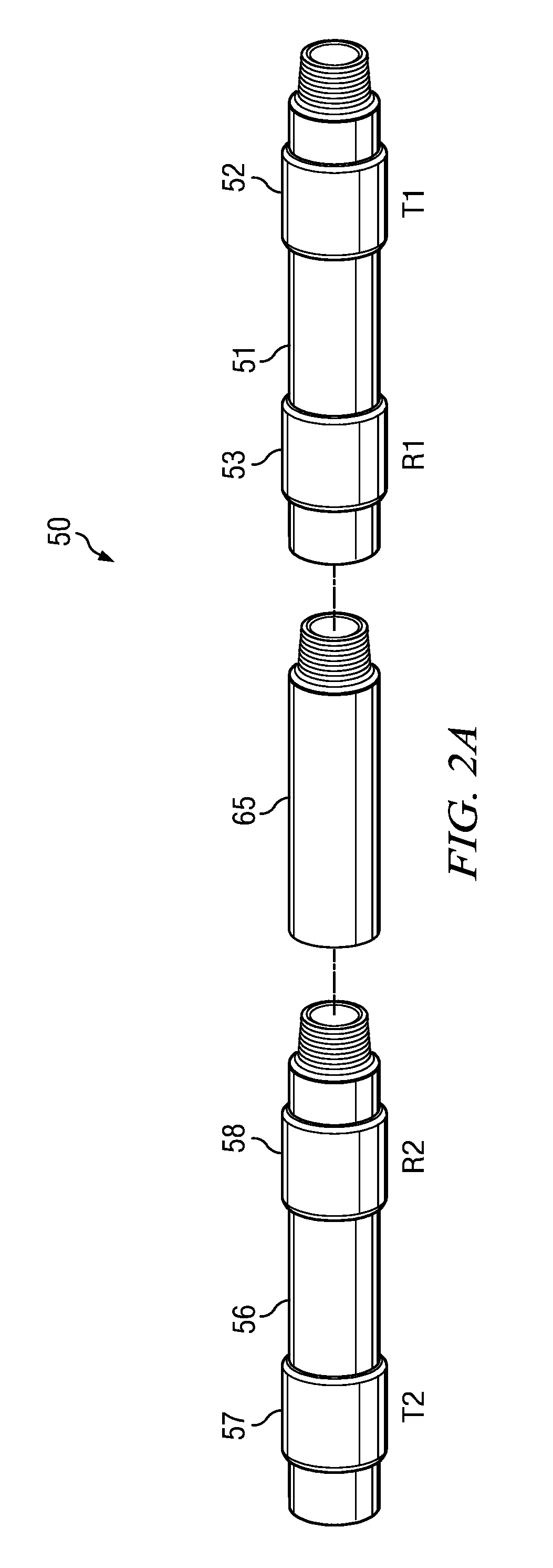
[0018]FIGS. 2A and 2B (collectively FIG. 2) depict electromagnetic measurement tool embodiment 50. In the embodiment depicted on FIG. 2A measurement tool 50 includes a first transmitter 52 and a first receiver 53 deployed on a first sub 51 and a second transmitter 57 and a second receiver 58 deployed on a second sub 56. The first and second subs 51 and 56 may be axially spaced apart substantially any suitable distance to achieve a desired measurement depth.

[0019]FIG. 2A further depicts a drilling motor 65 deployed between the first and second subs 51 and 56. The drilling motor may include, for example, a progressing cavity hydraulic motor (also referred to in the art as a Moineau style power section). Such motors are common in drilling operations (e.g., slide drilling and power drilling operations) and make use of hydraulic power from drilling fluid to provide torque and rotary power, for example, to a drill bit assembly located below the motor (and below sub 51). In the depicted em...

embodiment 100

[0025]FIG. 3A depicts a flow chart of one disclosed method embodiment 100. An electromagnetic measurement tool (e.g., measurement tool 50 on FIG. 2) is rotated in a subterranean wellbore at 110 such that the first and second subs rotate at different rates (e.g., such that the first sub rotates at a higher rate than the second sub). Electromagnetic measurements are acquired at 120 while the tool is rotating and processed to obtain harmonic voltage coefficients. Selected ones of the harmonic voltage coefficients are rotated mathematically at 130 to simulate rotation of the x and y antennas in the R1 and R2 receivers such that they are rotationally aligned with the x and y antennas in the T1 and T2 transmitters. Such rotation removes the effect of the offset angle α. The mathematical rotation of the harmonic voltage coefficients may further include rotation by θ1, θ2, or θ2−θ1 such that the R1 and R2 receiver measurements are rotationally aligned with one another (and / or with a global ...


PUM


Abstract

A method for making downhole electromagnetic logging while drilling measurements includes rotating an electromagnetic logging while drilling tool in a subterranean wellbore. The logging tool includes a first transmitter and a first receiver deployed on a first sub and a second transmitter and a second receiver deployed on a second sub. Rotating the logging tool causes the first and second subs to rotate at different rates. A plurality of electromagnetic voltage measurements are acquired from the first and second receivers while rotating. The acquired voltage measurements are processed to compute harmonic coefficients which are mathematically rotated to obtain rotated coefficients. Ratios of selected ones of the rotated coefficients are processed to compute gain compensated measurement quantities.

Description

CROSS REFERENCE TO RELATED APPLICATIONS[0001]None.FIELD OF THE DISCLOSURE[0002]Disclosed embodiments relate generally to downhole electromagnetic logging and more particularly to a method for making fully gain compensated deep propagation measurements, such as phase shift and attenuation measurements, while upper and lower antenna subs rotate at different rates.BACKGROUND INFORMATION[0003]The use of electromagnetic measurements in prior art downhole applications, such as logging while drilling (LWD) and wireline logging applications is well known. Such techniques may be utilized to determine a subterranean formation resistivity, which, along with formation porosity measurements, is often used to indicate the presence of hydrocarbons in the formation. Moreover, azimuthally sensitive directional resistivity measurements are commonly employed e.g., in pay-zone steering applications, to provide information upon which steering decisions may be made.[0004]Downhole electromagnetic measurem...

Claims


Application Information

Patent Timeline
Patent Type & Authority Patents(United States)
IPC IPC(8): G01V3/26G01V3/38G01V3/30
CPCG01V3/26E21B47/13
Inventor FREY, MARK
Owner SCHLUMBERGER TECH CORP
Why Eureka
Try Eureka