Syringe pump, and related method and system

a technology of syringe and syringe, which is applied in the direction of positive displacement liquid engine, medical information, instruments, etc., can solve the problems of rotational force of the securing arm

Active Publication Date: 2017-10-17
DEKA PROD LLP
View PDF446 Cites 93 Cited by
  • Summary
  • Abstract
  • Description
  • Claims
  • Application Information

AI Technical Summary

Benefits of technology

[0158]In some embodiments, the means configured for clamping any of a range of plunger flange sizes may comprise a cam, at least one cam follower, and at least one bias member. The bias member may bias said means configured for clamping any of a range of plunger flange sizes toward a first position. In some embodiments, movement of the at least one cam follower along the cam may overcome the bias member and allow the means configured for clamping any of a range of plunger flange sizes to move toward a second position.
[0170]In some embodiments, the clamping means may comprise a cam, at least one cam follower, and at least one bias member. The bias member may bias said clamping means toward a first position. Movement of the at least one cam follower along the cam may overcome the bias member and allow the clamping means to move toward a second position.
[0265]In accordance with an embodiment of the present disclosure a method for mitigating lead screw runout error may include tracking the rotations of a lead screw using a rotary position sensor. The method may include tracking distance output of a lead screw mechanism using a linear position sensor. The method may include converting the rotary position sensor output to a linear displacement output of the lead screw mechanism. The method may include creating error data by determining the difference between data from the linear position sensor and converted data from the rotary position sensor. The method may include estimating, based on the error data, a phase and amplitude of deviations from an assumed direct relation of rotations to distance output of the lead screw mechanism, using a processor. The method may include controlling, with a controller, the output of the lead screw mechanism. The controller may compensate for the estimated devaitions.
[0267]In accordance with an embodiment of the present disclosure, a system for mitigating lead screw runout may include a linear position sensor configured to track a distance output of a lead screw mechanism and generate distance data. A rotary position sensor configured to track rotations of the lead screw and generate rotational data may be included. A processor may be included. The processor may be configured to convert the rotational data into converted distance output of the lead screw mechanism. The processor may be configured to create error data by determining the difference between the converted rotational data and the distance data. The processor may be configured to estimate the amplitude and phase of the error data. A controller configured to control the distance output of the lead screw mechanism may be included. The controller may compensate for the phase and amplitude of the error data.

Problems solved by technology

When the second arm engages the plate, the force of the spring and the shape of the plate persuades the arm to rotate, ultimately resulting in the rotational force of the securing arm.
The shape of the plate combined with the force of the spring persuades the arm to rotate, ultimately resulting in the rotational force of the securing arm.

Method used


Image

  • Syringe pump, and related method and system
  • Syringe pump, and related method and system
  • Syringe pump, and related method and system

Examples


Embodiment Construction

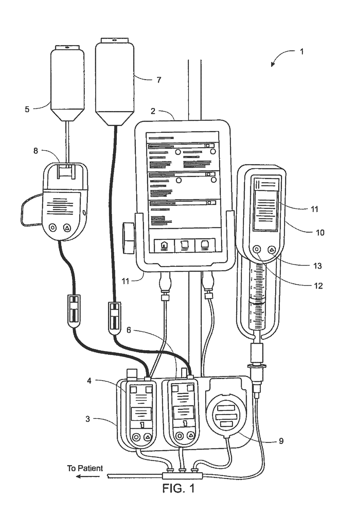
[0410]FIG. 1 shows an exemplary arrangement of a system 1 for electronic patient care in accordance with an embodiment of the present disclosure. The system 1 includes a monitoring client 2 that is linked to a number of patient-care devices via docks 3 and 11, including an infusion pump 4 connected to and delivering from a smaller bag of liquid 5, an infusion pump 6 connected to and delivering from a larger bag of liquid 7, a drip detection device 8 connected to tubing from the smaller bag 5, and a microinfusion pump 9. System 1 also includes a syringe pump 10 connected wirelessly to the monitoring client 2. In some embodiments, the monitoring client 2 may communicate with these patient-care devices in a wired fashion, as shown in FIG. 1 for the infusion pumps 4 and 6, and the microinfusion pump 9 (via docks 3 and 11). Additionally or alternatively, the monitoring client 2 may communicate wirelessly with patient-care devices, as suggested by the absence of a wired connection between...


PUM


Abstract

A method for discharging fluid from a syringe and for mitigating occlusion conditions includes actuating the plunger of a syringe into a barrel. The method monitors fluid pressure within the barrel of the syringe and determines that an occlusion exists when the fluid pressure exceeds a predetermined threshold. The method actuates the plunger out of the barrel by a predetermined amount in response to the detected occlusion and actuates the plunger of the syringe into the barrel until a measured fluid pressure within the barrel of the syringe exceeds another predetermined threshold.

Description

CROSS-REFERENCES TO RELATED APPLICATIONS[0001]The present application is a Non-Provisional Application which claims the benefit of U.S. Provisional Patent Application Ser. No. 61 / 904,123, filed Nov. 14, 2013 and entitled Syringe Pump and Related Method; and U.S. Provisional Patent Application Ser. No. 61 / 894,801, filed Oct. 23, 2013 and entitled Syringe Pump and Related Method, each of which is hereby incorporated herein by reference in its entirety.[0002]The present application is also a Continuation-In-Part of U.S. patent application Ser. No. 13 / 833,432, filed Mar. 15, 2013 and entitled Syringe Pump and Related Method, now U.S. Publication No. US-2013-0281965-A1, published Oct. 24, 2013, which claims priority to and the benefit of the following:[0003]U.S. Provisional Patent Application Ser. No. 61 / 679,117, filed Aug. 3, 2012 and entitled System, Method, and Apparatus for Monitoring, Regulating, or Controlling Fluid Flow; and[0004]U.S. Provisional Patent Application Ser. No. 61 / 651...

Claims


Application Information

Patent Timeline
Patent Type & Authority Patents(United States)
IPC IPC(8): A61M5/145A61M5/172G06F19/00A61M5/14A61M5/168G16H20/17G16H40/67G16H70/40
CPCA61M5/1452A61M5/1408A61M5/1413A61M5/1456A61M5/1458A61M5/16827A61M5/16831A61M5/172G06F19/323G06F19/326G06F19/3406G06F19/3418G06F19/3468A61M2205/12A61M2205/14A61M2205/18A61M2205/332A61M2205/3306A61M2205/3317A61M2205/3576A61M2205/50A61M2205/505A61M2205/52A61M2209/082A61M2209/086G16H40/63G16H10/65G16H70/40G16H20/17G16H40/67A61M5/1415F04B1/26
Inventor KAMEN, DEANGRAY, LARRY B.BODWELL, JESSE T.KERWIN, JOHN M.BAIER, MICHAEL J.VAN DER MERWE, DIRK A.FICHERA, STEPHEN L.THURBER, JONATHAN R.DESCH, MARTIN D.
Owner DEKA PROD LLP
Why Eureka
Try Eureka